Abstract: This application note describes how to develop, build, and debug applications for the MAXQ1103 microcontroller. This application note uses the CrossWorks C compiler provided by Rowley Associates for the MAXQ30 platform.
Introduction MAXQ1103 is a new generation of secure microcontrollers from Maxim Integrated Products, designed for financial terminals. It runs 16-bit instructions and provides a 32-bit data channel. The microcontroller executes complete instructions in one machine cycle and is a very high-performance RISC machine. MAXQ1103 also has many important security features, including: DES, 3DES, SHA-1, SHA-224, SHA-256, RSA, DSA, and ECDSA crypto accelerator. Real hardware random number generator 1KB low-leakage battery backup NVSRAM Seven anti-tamper detection input environmental sensors connected to external circuits, such as temperature and voltage overrange detector MAXQ1103 evaluation (EV) kit, are ideal platforms for prototype development of security applications. The kit provides two serial ports, two smart card slots (one full size, one SIM card), a USB connector, an LCD screen, a 16-key keyboard and a prototype area.
Setting up the MAXQ1103 evaluation kit The MAXQ1103 evaluation kit is shown in Figure 1. The hardware components listed below are required to complete the work discussed in this application note: MAXQ1103 Evaluation Kit Circuit Board JTAG Circuit Board JTAG Cable (Connect MAXQ1103 Evaluation Kit Circuit Board and JTAG Circuit Board) 9-pin Serial Cable Regulated Power Supply (5V , ± 5%, 300mA, center positive)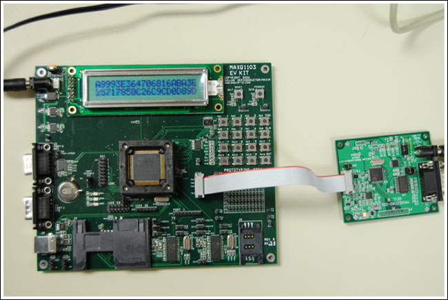
Detailed circuit diagram (PDF, 14.4MB)
Figure 1. The MAXQ1103 evaluation kit
Both the MAXQ1103 evaluation kit circuit board and the JTAG circuit board have many jumpers that need to be configured. If you need detailed information about jumpers and their functions, please refer to their respective data sheets. For this application note, please configure the jumper according to the following requirements: On the MAXQ1103 evaluation kit circuit board, short jumper JU1 and connect the two pins on JU5 (the two pins closest to the JU5 label). Now all other jumpers should be opened. If all jumpers from JU6 to JU18 are shorted, then OK. This is the configuration required for smart card communication and is not covered in this application note. On the JTAG circuit board, short-circuit JH1 and JH2, and open JH3. Connect the JTAG cable between the JTAG board and the MAXQ1103 kit board. On the JTAG circuit board, the red cable should be connected to the side marked with pins 1 and 2 and to the TCK-GND side of the MAXQ1103 kit circuit board.
Note that in the early MAXQ1103 evaluation kit, the MAXQ1103 IC may have used a slot. If this is the case, insert the MAXQ1103 into the IC marked downward slot (lead-free indicator "+" should be on the upper right side).
Connect a 9-pin serial cable between your PC and JTAG board. Do not connect it to the MAXQ1103 evaluation kit board. Connect the power supply to these two boards.
Design using the CrossWorks compiler: Blinky, instead of starting with "Hello World", build a simple application that blinks an LED on the MAXQ103 kit circuit board.
The toolkit we used was CrossStudio provided by Rowley Associates. Now, the current version of the toolkit is CrossWorks (version 2.0.0.2008063000.2293) for MAXQ30, which can be used to generate a screenshot of this document. To determine whether it is the latest version, please visit the Rowley Associates website online, or contact us through the Maxim Support Center.
When creating a new solution, click File New New Project. In the New Project pop-up box, fill in the Name and LocaTIon boxes at the bottom and select “AC executable†from the Project Templates window (Figure 2). We call the project BlinkyDemo and put it in the directory C: \ work \ maxq \ maxq1103 \ blinky.
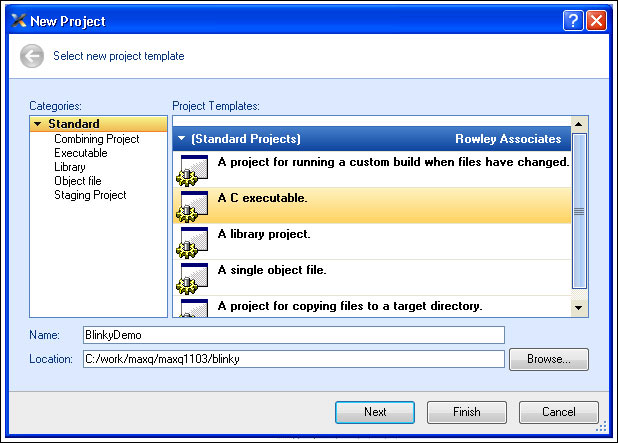
Figure 2. Select "AC executable" and fill in the project name and location
Click Next to continue and you will see the Project ProperTIes pop-up box. Just select the default value, click Finish to build the project (you can click Next to select other options; this project uses all default values ​​in these options).
When creating a project, a new project (Figure 3) will appear in the Project Explorer box, usually located in the upper right of the application window. Open it and you will see two folders, Source Files and System Files. Open Source Files and you will see main.c, which is the source code of your application. Double-click it to open it.
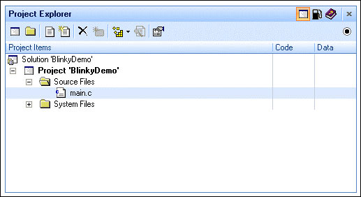
Figure 3. Project Explorer window
The automatically generated source code is very simple, we only need to add a few lines to make our blinking application work. Copy the following application code (replace all current contents in main.c file). #include #include void delayms (unsigned long count) {unsigned int x; while (count> 0) {for (x = 0; x <2500; x ++) {__no_operaTIon ();} count--;}} void main (void) {/ / set port 0 to all output PD0 = 0xff; while (1) {// toggle bits 0, 1, 7 PO0 = PO0 ^ 0x83; delayms (500);}} When we run this application, we will see LEDs DS1, DS2, and DS3 (located on the lower left side of the kit board MAXQ1103) flash, turn on for 0.5s, and turn off for 0.5s. Note that the "delayms" function is not exactly one millisecond, but is very close, achieving the purpose of blinky applications.
Before running the demo, you must first build it. Choose Build Build BlinkyDemo. Or press F7 to build. If everything is built correctly, you will see the message "Build complete" in the Output window with a check mark next to it (Figure 4). If there are errors, please make sure that the code you entered is correct.
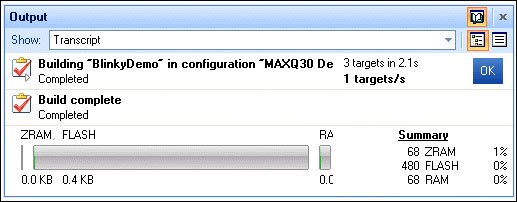
Figure 4. Output after project construction
When running the application, click Debug Step Over. You can also press F10, or click the icon in the toolbar with a downward arrow (Figure 5).
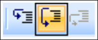
Figure 5. Step Over button
CrossStudio downloads the application to the MAXQ1103 through the JTAG circuit board, and the Output window displays status messages. The application will start running and then stop at the first line of code (yellow arrow in the blank area on the left). When running the application, click the "Play" button (or select Debug Go). Now, make sure that the LEDs on the MAXQ1103 circuit board are blinking. You may want to be able to modify the application to some extent. Make the LEDs blink in sequence, or change the lighting time to blink faster or slower.
Debugging applications with CrossStudio Now, let's understand the debugging features of the MAXQ1103 and CrossStudio tools. MAXQ1103 has a built-in JTAG engine, which supports debugging on the actual chip, so that it does not require expensive emulators or emulators that may go wrong. Note that the MAXQ1103 also provides a locking mechanism to prevent JTAG from working when the component is locked. In this way, when the MAXQ1103 microcontroller is used in sensitive applications, it ensures that the JTAG debugging engine does not pose a security threat.
Now, we return to the original Blinky application. In the main function, change the delay from 500 to 5: delayms (5); Now, build and run the application. Note that the LED lights continuously, rather than blinking constantly. This is the case when the simple demo code is first written and run.
This brings up a basic question: "Is the lamp really lit continuously, or is it flashing very fast without being noticeable?" If the lamp is lit continuously, it is necessary to check the schematic and pin assignment to make sure everything is OK. If the LED just flashes quickly (too fast to see the interval clearly), then only the time needs to be adjusted, which is probably the work that needs to be done. To answer this question, we now use CrossStudio's debugging tools.
Press the Pause button (or select Debug Break). Where the code stops, a yellow arrow appears. The code is likely to stop in the 'for' loop of the delayms () function (see Figure 6).
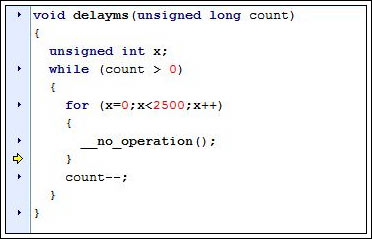
Figure 6. In the delayms () function, the code stops running
Observe the Locals window on the right (if you cannot see this window, click Debug Debug Windows Locals). The window will display the current values ​​of the variables "x" and "count". Now, press the Step Over button a few times. In the Locals window, you should see the x value increase (you can continue to press Step Over until the end of the cycle, but this may take a long time).
Now, it is easy to answer the question "Is the light blinking?" For this, you need to set a breakpoint on the delayms (5) line of the main function, and click the small triangle to the left of the code line. It will turn into a red circle (Figure 7). Now, run the application again (Debug Go, or Play button). The application will run to this point and then pause. Now, after clicking Go several times, you will see that with your click, the light turns on and off. This verified that the light was flashing, but it was too fast for our eyes to notice.
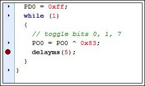
Figure 7. Add breakpoint
Now, we take this opportunity to learn more about debugging features. Press the Step Over button several times and execute three lines of code in sequence: while (1), PO0 = PO0 ^ 0x83 and delayms (5). You will see that the light flashes when passing the PO0 line. Now, when paused in the delayms (5) line, press the Step Into button (Figure 8) to enter the delayms () function (instead of Step Over, which will execute the entire function).
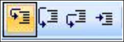
Figure 8. Step Into button
At runtime, you can also change variables (and registers). Clear all breakpoints (Debug Breakpoints Clear All Breakpoints), click Go. Click Pause, and the program should stop again in the middle of the delayms () function. Note the "x" and "count" values. Now, set x to 2499 (click the value displayed by x, and highlight and enter 2499). Perform Step Over or Step Into several times, you will see the end of the loop, and the "count" value also decreases.
And other debugging features that interest you: Debug Disassembly will display both the C code and the generated assembly code. In this way, the user can enter the assembly code instead of the C code, and at the same time know where the C code corresponds. Debug Debug Windows Call Stack will display the function called when the application reaches the current position. If execution is suspended in the delayms () function, its display is shown in Figure 9. Use Debug Stop to stop debugging and observe the Targets window on the right. Make sure the Maxim Serial JTAG Adapter is displayed in bold, and observe the configuration options below. If you use a serial port instead of the default COM1, you can change this option here. 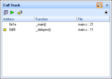
Figure 9. Call stack while running in delayms () function
More information Software libraries and reference designs are currently being developed by Maxim engineers. If you need the latest information about libraries and tools, or if you have any questions about this application note, please contact var name = "microcontroller.support @"; var domain = "maxim-ic.com"; document.write ("" + name + domain + ""); microcontroller. (English only).
Introduction MAXQ1103 is a new generation of secure microcontrollers from Maxim Integrated Products, designed for financial terminals. It runs 16-bit instructions and provides a 32-bit data channel. The microcontroller executes complete instructions in one machine cycle and is a very high-performance RISC machine. MAXQ1103 also has many important security features, including: DES, 3DES, SHA-1, SHA-224, SHA-256, RSA, DSA, and ECDSA crypto accelerator. Real hardware random number generator 1KB low-leakage battery backup NVSRAM Seven anti-tamper detection input environmental sensors connected to external circuits, such as temperature and voltage overrange detector MAXQ1103 evaluation (EV) kit, are ideal platforms for prototype development of security applications. The kit provides two serial ports, two smart card slots (one full size, one SIM card), a USB connector, an LCD screen, a 16-key keyboard and a prototype area.
Setting up the MAXQ1103 evaluation kit The MAXQ1103 evaluation kit is shown in Figure 1. The hardware components listed below are required to complete the work discussed in this application note: MAXQ1103 Evaluation Kit Circuit Board JTAG Circuit Board JTAG Cable (Connect MAXQ1103 Evaluation Kit Circuit Board and JTAG Circuit Board) 9-pin Serial Cable Regulated Power Supply (5V , ± 5%, 300mA, center positive)
Detailed circuit diagram (PDF, 14.4MB)
Figure 1. The MAXQ1103 evaluation kit
Both the MAXQ1103 evaluation kit circuit board and the JTAG circuit board have many jumpers that need to be configured. If you need detailed information about jumpers and their functions, please refer to their respective data sheets. For this application note, please configure the jumper according to the following requirements: On the MAXQ1103 evaluation kit circuit board, short jumper JU1 and connect the two pins on JU5 (the two pins closest to the JU5 label). Now all other jumpers should be opened. If all jumpers from JU6 to JU18 are shorted, then OK. This is the configuration required for smart card communication and is not covered in this application note. On the JTAG circuit board, short-circuit JH1 and JH2, and open JH3. Connect the JTAG cable between the JTAG board and the MAXQ1103 kit board. On the JTAG circuit board, the red cable should be connected to the side marked with pins 1 and 2 and to the TCK-GND side of the MAXQ1103 kit circuit board.
Note that in the early MAXQ1103 evaluation kit, the MAXQ1103 IC may have used a slot. If this is the case, insert the MAXQ1103 into the IC marked downward slot (lead-free indicator "+" should be on the upper right side).
Connect a 9-pin serial cable between your PC and JTAG board. Do not connect it to the MAXQ1103 evaluation kit board. Connect the power supply to these two boards.
Design using the CrossWorks compiler: Blinky, instead of starting with "Hello World", build a simple application that blinks an LED on the MAXQ103 kit circuit board.
The toolkit we used was CrossStudio provided by Rowley Associates. Now, the current version of the toolkit is CrossWorks (version 2.0.0.2008063000.2293) for MAXQ30, which can be used to generate a screenshot of this document. To determine whether it is the latest version, please visit the Rowley Associates website online, or contact us through the Maxim Support Center.
When creating a new solution, click File
New New Project. In the New Project pop-up box, fill in the Name and LocaTIon boxes at the bottom and select “AC executable†from the Project Templates window (Figure 2). We call the project BlinkyDemo and put it in the directory C: \ work \ maxq \ maxq1103 \ blinky. Figure 2. Select "AC executable" and fill in the project name and location
Click Next to continue and you will see the Project ProperTIes pop-up box. Just select the default value, click Finish to build the project (you can click Next to select other options; this project uses all default values ​​in these options).
When creating a project, a new project (Figure 3) will appear in the Project Explorer box, usually located in the upper right of the application window. Open it and you will see two folders, Source Files and System Files. Open Source Files and you will see main.c, which is the source code of your application. Double-click it to open it.
Figure 3. Project Explorer window
The automatically generated source code is very simple, we only need to add a few lines to make our blinking application work. Copy the following application code (replace all current contents in main.c file). #include
Before running the demo, you must first build it. Choose Build
Build BlinkyDemo. Or press F7 to build. If everything is built correctly, you will see the message "Build complete" in the Output window with a check mark next to it (Figure 4). If there are errors, please make sure that the code you entered is correct. Figure 4. Output after project construction
When running the application, click Debug
Step Over. You can also press F10, or click the icon in the toolbar with a downward arrow (Figure 5). Figure 5. Step Over button
CrossStudio downloads the application to the MAXQ1103 through the JTAG circuit board, and the Output window displays status messages. The application will start running and then stop at the first line of code (yellow arrow in the blank area on the left). When running the application, click the "Play" button (or select Debug
Go). Now, make sure that the LEDs on the MAXQ1103 circuit board are blinking. You may want to be able to modify the application to some extent. Make the LEDs blink in sequence, or change the lighting time to blink faster or slower. Debugging applications with CrossStudio Now, let's understand the debugging features of the MAXQ1103 and CrossStudio tools. MAXQ1103 has a built-in JTAG engine, which supports debugging on the actual chip, so that it does not require expensive emulators or emulators that may go wrong. Note that the MAXQ1103 also provides a locking mechanism to prevent JTAG from working when the component is locked. In this way, when the MAXQ1103 microcontroller is used in sensitive applications, it ensures that the JTAG debugging engine does not pose a security threat.
Now, we return to the original Blinky application. In the main function, change the delay from 500 to 5: delayms (5); Now, build and run the application. Note that the LED lights continuously, rather than blinking constantly. This is the case when the simple demo code is first written and run.
This brings up a basic question: "Is the lamp really lit continuously, or is it flashing very fast without being noticeable?" If the lamp is lit continuously, it is necessary to check the schematic and pin assignment to make sure everything is OK. If the LED just flashes quickly (too fast to see the interval clearly), then only the time needs to be adjusted, which is probably the work that needs to be done. To answer this question, we now use CrossStudio's debugging tools.
Press the Pause button (or select Debug
Break). Where the code stops, a yellow arrow appears. The code is likely to stop in the 'for' loop of the delayms () function (see Figure 6). Figure 6. In the delayms () function, the code stops running
Observe the Locals window on the right (if you cannot see this window, click Debug
Debug Windows Locals). The window will display the current values ​​of the variables "x" and "count". Now, press the Step Over button a few times. In the Locals window, you should see the x value increase (you can continue to press Step Over until the end of the cycle, but this may take a long time). Now, it is easy to answer the question "Is the light blinking?" For this, you need to set a breakpoint on the delayms (5) line of the main function, and click the small triangle to the left of the code line. It will turn into a red circle (Figure 7). Now, run the application again (Debug
Go, or Play button). The application will run to this point and then pause. Now, after clicking Go several times, you will see that with your click, the light turns on and off. This verified that the light was flashing, but it was too fast for our eyes to notice. Figure 7. Add breakpoint
Now, we take this opportunity to learn more about debugging features. Press the Step Over button several times and execute three lines of code in sequence: while (1), PO0 = PO0 ^ 0x83 and delayms (5). You will see that the light flashes when passing the PO0 line. Now, when paused in the delayms (5) line, press the Step Into button (Figure 8) to enter the delayms () function (instead of Step Over, which will execute the entire function).
Figure 8. Step Into button
At runtime, you can also change variables (and registers). Clear all breakpoints (Debug
Breakpoints Clear All Breakpoints), click Go. Click Pause, and the program should stop again in the middle of the delayms () function. Note the "x" and "count" values. Now, set x to 2499 (click the value displayed by x, and highlight and enter 2499). Perform Step Over or Step Into several times, you will see the end of the loop, and the "count" value also decreases. And other debugging features that interest you: Debug
Disassembly will display both the C code and the generated assembly code. In this way, the user can enter the assembly code instead of the C code, and at the same time know where the C code corresponds. Debug Debug Windows Call Stack will display the function called when the application reaches the current position. If execution is suspended in the delayms () function, its display is shown in Figure 9. Use Debug Stop to stop debugging and observe the Targets window on the right. Make sure the Maxim Serial JTAG Adapter is displayed in bold, and observe the configuration options below. If you use a serial port instead of the default COM1, you can change this option here. Figure 9. Call stack while running in delayms () function
More information Software libraries and reference designs are currently being developed by Maxim engineers. If you need the latest information about libraries and tools, or if you have any questions about this application note, please contact var name = "microcontroller.support @"; var domain = "maxim-ic.com"; document.write ("" + name + domain + ""); microcontroller. (English only).
Digital Desk Clock,Digital Clock For Desk,Table Digital Clock,Movie Clapper Digital Clock
Guangzhou Huanyu Clocking Technologies Co., Ltd. , https://www.findclock.com