Research and Implementation of Wireless Drive Test System Based on Railway Special Communication GSM-R
0 Preface
GSM-R is a special communication system based on GSM technology-railway integrated digital mobile communication system. Compared with the traditional GSM technology, GSM-R can not only provide a series of railway communication services, but also ensure that the train can carry out high-reliability, high connection rate and high transmission quality communication at 500 km / h. At present, GSM-R technology has become the focus of international and domestic railway communication development, and China has also made certain progress in GSM-R technology. In 2004, the planning, construction and trial operation of the GSM-R railway special communication network were started in the electrification transformation of the Qinghai-Tibet Railway, the Daqin Line and the construction of the Jinghu High-speed Railway. At the same time, as the current domestic GSM-R drive test system is very scarce, optimizing the GSM-R wireless network has also become a top priority in the construction of GSM-R mobile communication networks. In order to truly understand the GSM-R network, commission the GSM-R network, and optimize the GSM-R network, this paper proposes and designs a wireless drive test system that is suitable for both the GSM network and the GSM-R network. On the one hand, in the early stage of GSM-R network construction, the frequency allocation and cell parameter adjustment can be reasonably performed through the assistance of this system: on the other hand, the performance of the established GSM and GSM-R networks can be optimized and the communication quality can be improved.
1 Introduction to GSM-R network
1.1 Network structure and function
A GSM-R mobile communication network is composed of several functional entities. The set of functions realized by each functional entity is the basic service and supplementary service provided to users by the GSM-R network. The GSM-R mobile communication network structure is based on the GSM mobile communication network, which is mainly composed of three parts: the base station subsystem (BSS), the network subsystem (NSS), and the operation and maintenance subsystem (OSS). Its basic structure is shown in FIG.
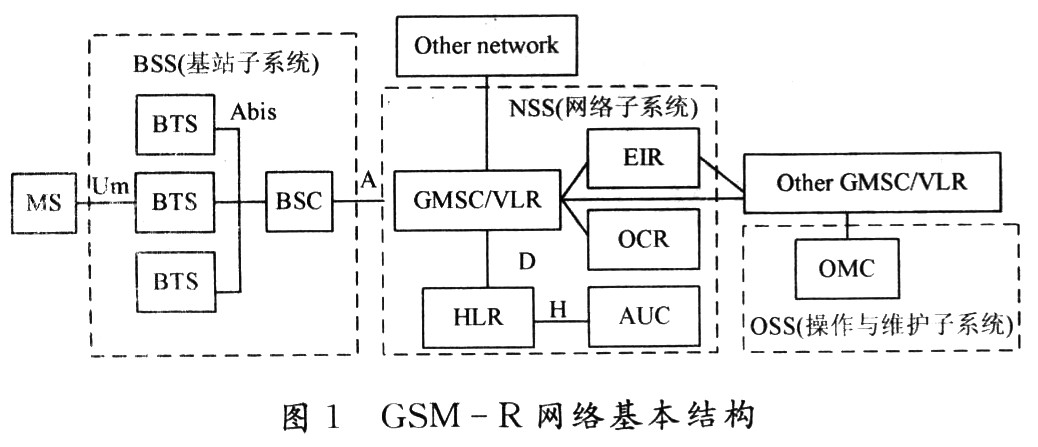
The BSS is mainly composed of a base station controller (BSC) and a base transceiver station (BTS). It is connected to the mobile station (MS) through the wireless interface (Um), and the A interface is connected to the NSS. BTS is a relay for communication between the fixed part of the network and the wireless part. The MS connects with the BTS through the air interface. It is the wireless access part of the mobile communication network and the part where the end user feels the network quality most directly. One or several BTSs are connected to a BSC. The BSC mainly provides the functions of radio resource management and mobility management in its coverage area, as well as the operation and maintenance functions of the radio network. BSS may also have a coding rate adaptation unit (TRAU) to achieve coding rate conversion.
NSS generally consists of six functional entities, namely mobile switching center (MSC), home location register (HLR), visiting location register (VLR), authentication center (AUC), equipment identification register (EIR), group call register ( GCR). NSS is mainly responsible for end-to-end calls, user data management, mobility management and fixed network connection. Among them, MSC is the core of NSS, which is used to establish business channels and exchange signaling messages between MSCs or other networks. Connected to the MSC is the VLR, which manages a dynamic database of roaming mobile user information in an MSC area. HLR stores the static information of mobile users permanently registered in the network, such as user information, bearer and customized user information. AUC completes user authentication and encrypts wireless communication between the mobile station and the network. EIR is used to store IMEI (International Mobile Equipment Identifier). GCR, a unique component of the GSM-R network, is used to store the group ID of the mobile user, cell information referenced by the mobile station to initiate a voice group call (VGCS) and voice broadcast (VBS), and an indication whether the MSC that initiated the call is responsible for processing the call.
OSS can be divided into OMC-R corresponding to the BSS operation and maintenance center and OMC-S corresponding to the NSS operation and maintenance center. OSS is an intermediary between operators and system equipment, which realizes the centralized operation and maintenance of the system. Completed functions including mobile user management, mobile device management and network operation and maintenance. It is connected to the device on one side and a computer workstation as a human-machine interface on the other side. These equipment dedicated to operation and maintenance are called the operation and maintenance center OMC. Each component of the system can be connected to OMC through a unique network to achieve centralized maintenance.
1.2 Business Model
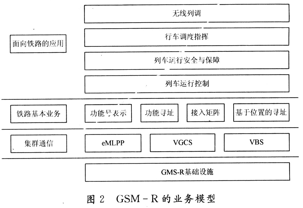
GSM-R is a comprehensive dedicated digital mobile communication system designed specifically for railway communications. It is based on the GSM infrastructure and the advanced voice call services it provides, including enhanced multi-priority and strong teardown (eM-LPP), VGCS and VBS. And provide railway-specific dispatching services, including: function addressing, function number representation, access matrix and location-based addressing. And use this as an information platform, so that the railway part can develop various applications on this information platform. The business model of GSM-R is shown in Figure 2.
2 Wireless interface protocol
The wireless interface (Um) is a communication interface between the MS and the BTS, also known as the air interface (airinteRFace). It is used for the communication between the mobile station and the fixed part of the GSM-R system, and its physical connection is realized through a wireless link. The information transmitted by this interface includes wireless resource management, mobility management, and connection management.
2.1 Protocol layering (three layers)
The air interface corresponds to the lower three layers of the OSI (Open System Interconnection) model, and is divided into a physical layer, a link layer, and a network layer. The hierarchical model of OSI does not correspond strictly.
Physical layer (PHL): Support TDMA frame, FDMA and logical channel multiplexing. Provide wireless channel transmission channels, and provide high-level logical channels with different functions, such as service channels and control channels. The physical layer is responsible for the sending and receiving of data or data packets under the control of the MAC layer.
Link layer: includes the medium access control layer MAC and the data link control layer (DLC). The former provides different services for higher layers by forming multiple logical channels; the latter provides very reliable data links for the network layer. Provides a very reliable transmission link for internal control signaling and a limited number of user information.
Network layer: mainly the signaling layer, including connection management (CM), mobility management (MM), and radio resource management (RM). Various functions such as link control, call control, additional service, connection-oriented message service, and connectionless message service are determined.
2.2 Working mode of wireless resources
The purpose of radio resource management is to establish, maintain, and release radio resource (RR) connections for point-to-point calls between the network and mobile stations. An RR connection is a physical connection between two equal entities that is used to support changes in information traffic between upper layers. The wireless resource management mainly provides four working modes to the upper layer, namely: idle mode, dedicated mode, group sending mode, and group receiving mode.
Idle mode: No dedicated channel is allocated to any MS, and there is no RR connection. At this time, the MS can only receive broadcast messages of CCCH (common control channel) and BCCH (broadcast control channel) channels. The MS analyzes the received paging message and broadcast message, and chooses to camp on the cell with the strongest signal strength. The MS corresponds to the standby state.
Dedicated mode: At least two dedicated channels are allocated to the MS, and only one of them is SACCH (Slow Speed ​​Associated Control Channel). MS and BTS have established a two-way point-to-point physical connection at this time, which is used for information transmission. The RR connection can be maintained through automatic cell reselection and handover. The MS corresponds to the call state or the location update state. Group mode: Two dedicated channels are allocated for MSs in voice group call. These two channels can be allocated to one MS or to different MSs at the same time. The RR connection established by the MS and the BTS at this time is similar to the dedicated mode, but the signaling messages during the establishment process are different, specifically indicating that this mode is used for group communication. MS corresponds to the state of the speaker in VGCS or VBS.
Group reception mode: MS is not assigned a dedicated channel connected to the network. It receives the downlink broadcast message or voice group call channel downlink message assigned to the cell in an unanswered manner. At this time, MS corresponds to the state of the listener in VGCS or VBS.
3 GSM-R wireless drive test system
This system captures the signaling information of the communication between the MS and BTS in the Um port through monitoring, so as to obtain the wireless quality parameters of the GSM-R network, process the parameters in conjunction with the GSM-R wireless network optimization knowledge, and carefully design the display module. Intuitively and clearly present the network quality status to users, and finally give a performance report of the GSM-R network quality status.
3.1 Drive test environment
Network environment: satellite, GSM / GSM-R network; test instrument: one computer equipped with this system, one test mobile phone, one GPS, and several interface lines.
3.2 System acquisition parameters
(1) Network identification parameters
Mobile country number (MMC), mobile network number (MNC), location area code (LAC), cell identification (CI), network color code (NCC), base station color code (BCC).
(2) System control parameters
Common control channel configuration, access permission reserved blocks, paging channel multiframes, periodic location update timer, cell channel description, radio link timeout (RLT), neighbor cell description, allowed network color code, maximum retransmission The number of times (MR), the number of distributed distribution slots (TI), cell access barring (CBA), access level control (AC).
(3) Cell selection and reselection parameters
Cell reselection lag (CRH), control channel maximum power level (MT-MC), allowed access minimum receive level (RXLEVaccessmin), cell barring restriction (CBQ), cell reselection parameter indication (PI), cell reselection Offset (CRO), penalty time (PT), temporary offset (TO).
(4) Network function parameters
Power control indication (PERC), discontinuous transmission (DTX), call reestablishment permission (RE), emergency call permission (EC), mobile allocation index location (MAIO), frequency hopping sequence number (HSN).
(5) GPS parameters
latitude Longitude.
(6) Performance parameters
Call connection rate, call failure rate, channel utilization rate, allocation failure rate, dropped call rate, handover success rate, handover failure rate.
3.3 System functions
(1) Real-time tracking signaling
Able to track each logical control channel signaling in real time.
BCCH: including systeminformaTIon1, systeminforma-TIon2, etc .;
PCH (paging channel): including pagingrequest type1, pagin-grequest type2, etc .;
SACCH: including systeminformaTIon5, system-information6;
AGCH (Access Allowed Channel): including immediateteassign-ment, immediateteassignmentreject, etc .;
RACH (Random Access Channel): including channelrequest, up-linK_access.
In addition, it can also track layer 2 and layer 3 signaling: including: setup, alert-ting, disconnect, etc.
(2) Sweep test
In idle mode, all frequencies (GSM900 / GSM1800 / GSM-R, etc.) can be scanned in real time. Dynamically display the corresponding signal field strength and base station color code, and track the degree of interference of the occupied ARF-CN (absolute wireless frequency channel number) in real time. You can check the signal strength of neighboring cells, check the coverage of cells and interference with adjacent channels.
(3) Frequency lock test
In a dual-band network, the test phone will automatically select the channel with the stronger signal as the call network. If you encounter an area where the signal strength of a dual-band network is close, the line may be busy or "frequency hopping" (frequency hopping: constantly switching between two channels). Therefore, users want to make the mobile phone reception more stable and reduce the frequency hopping problem, they can use the "frequency lock" mobile phone operation function to observe the mobile station's reception level changes at a fixed frequency point.
(4) Forced switching
Forced handover is to allow the mobile station to forcibly hand over to another cell in the dedicated mode without satisfying the handover conditions. Use mandatory operations to collect the network quality status received by the MS. The mandatory areas are mainly the neighboring areas of each cell. It is used to discover the rationality and correctness of the network cell planning. Whether the actual coverage area of ​​some cells exceeds the planned area, and also You can switch signaling and analyze the cause of dropped calls.
(5) GSM / GSM-R base station opening test
After the implementation of the network plan, it is often necessary to test the signal coverage of the base station to find blind spots. The system can collect the signal strength changes of the current cell and the neighbor cell in real time. The system supports GPS positioning system, which can print the current location in real time, combined with the DT (vehicle test) network test method, can get the signal strength, base station identification code, absolute frequency point, signal of any collection point on the route that the car passes strength.
(6) Find various network problems based on signaling analysis
Because this system can collect network parameters and wireless signaling in real time, it can be used in network optimization to obtain the best benefits for network resources. Signaling includes: paging, authentication, encryption, channel allocation, handover, measurement report, location update, which can clearly show the signaling process of the call start, handover, location update, end call and dropped calls. Comparing the signaling collected on-site with the standard signaling process of GSM-R services, it can locate network failures such as call drop, TCH (service channel) congestion, and SDCCH (independent dedicated control channel) congestion.
(7) Calling and statistics of high volume traffic on dual phones
In the process of network optimization, large-volume test is often used to obtain performance parameters such as call connection rate, dropped call rate, call failure rate, and handover success rate to understand the robustness and feasibility of the network. The system supports the test of mutual call between two mobile phones. Through the automatic dialing function, the parameters such as number of calls, duration, and called number are set. After the call is completed, playback and call statistics can be provided.
(8) Test GSM-R unique services
GSM-R specific services include VGCS, VBS, etc. Ordinary GSM drive test system is not applicable in GSM-R network. The system can collect parameters and capture signaling for GSM-R unique services.
4 Conclusion
On the basis of summarizing and analyzing the GSM-R network structure, business model, wireless interface protocol and other theories, the purpose of wireless drive test and the significance of network optimization are discussed, and a new type of wireless communication for railway is given. System——Wireless drive test system of GSM / GSM-R network. This system provides an effective tool for GSM / GSM-R network optimization workers.
Quickly brew the perfect cup of tea or make pour over coffee right at the table with the Electric Tea Kettle. With 1500 watts, this Electric Kettle boils water faster than a microwave, and is safer to use than a stovetop kettle because it automatically turns off when the water reaches a boil. Serving at the table is no problem as the kettle lifts off the base without the cord. Additional features include two water level windows and a pull-lid to make filling and serving easy.
Features:
- Thermostat Control – Having a thermostat control allows the kettle to [know" when to shut off. This will prevent damage to the heating element and is an important feature in all modern styles.
- Auto shut off/Boil Dry Protection/Fuse – these are three features that are great for protecting the safety of users as well as extending the life of the electric kettle. The fuse and boil dry protection shut the kettle off if the water gets down below a certain level or if it`s left on for an extended period of time, It doesn`t burn up the kettle.
- Colors and Designs – Electric kettles come in all shapes, sizes and colors. Finding one that will fit with the kitchen design is actually pretty easy. Finding one that matches and that has the features you`re looking for can be a bit harder, but with all the choices available and the newer models on the market today, you will be able to find the perfect electric kettle for your kitchen.
- Savety in Electric- the heating element is typically fully enclosed, with a power rating of 2–3 kW at 220V. In countries with 110V mains electricity, kettles may be less powerful (1–1.5 kW) to avoid drawing too much current and requiring a very thick supply wire.
Application:
Heat the tea thoroughly
Bottle the water/beer
Boil water
Electric Tea Kettle
Electric Tea Kettle,Stainless Steel Electric Tea Kettle,Cordless Electric Tea Kettle,Electric Cordless Glass Tea Kettle
Guangzhou Taipeng Electrical Appliances Technology CO., LTD. , https://www.kettles.pl