Production and circuit design of highly sensitive wireless FM microphone
Here we introduce a highly sensitive wireless FM microphone, which can pick up the weak sound within 5 meters, and the transmission distance can reach about 500 meters. Its working frequency is in the range of 88 ~ 108Mhz, and its transmitted signal can be received through FM radio. Another feature of this wireless microphone is that the operating frequency is very stable, even if you touch the transmitting antenna with your hand, it will not cause changes in the transmitting frequency. It can be used for home entertainment, baby sleep monitoring and indoor and outdoor sound monitoring.
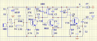
Circuit principle The circuit of the highly sensitive wireless microphone is shown in the figure,

The circuit is composed of acoustic-electric conversion, pre-emphasis circuit, audio amplification circuit, modulator and high-frequency power amplifier. The acoustic-electric converter is served by an electret condenser microphone. He picks up the acoustic signals of the surrounding environment and outputs the corresponding electrical signals. After C1, it is sent to the pre-emphasis circuit composed of R2 and C2 for bandwidth compression to improve the modulation quality of voice (corresponding to the de-emphasis in FM radio). VT1 is an audio amplifier that amplifies the pre-emphasized audio signal and sends it to the base of VT2 through C3 for frequency modulation. VT2 constitutes a common base ultra-high frequency oscillator, the voltage of the base and collector changes with the change of the audio signal input from the base, so that the junction capacitance of the base and collector changes, and the frequency of the high-frequency oscillator also changes with Change to achieve frequency modulation.
VT3 constitutes a class C high-frequency power amplifier with emitter output, which has two functions: one is to increase the transmission power and extend the transmission distance; the other is to isolate the antenna from the oscillator and reduce the influence of the antenna on the oscillator oscillation frequency. The signal after the high-frequency power amplifier is output by the emitter of VT3, and sent to the antenna through C10 and L3 for transmission. L3 is the antenna plus sense coil, used when the length of the antenna is less than one-quarter wavelength to improve the antenna's transmission efficiency. The capacity of C8 and C10 can not be greater than 20PF, otherwise the change of the antenna will cause frequency instability.
Component selection and production VT1 can use 9014, VT2 can use 9018, require magnification greater than 80; VT3 selects 8050C or 3DG12C, requires magnification greater than 50
C1, C3, C11 use electrolytic capacitors, C4 ~ C10 are ceramic capacitors, resistors use carbon film resistors, L1 ~ L3 with a diameter of 0.4mm enameled wire around the ballpoint pen core 6 turns, and then removed from the tire. L1 should be tapped at the 3rd place, and L2 and L3 should be arranged vertically on the printed circuit board. The antenna is best used as a whip antenna, but it can also be replaced with a plastic cord that is 800 mm long.
The printed circuit board diagram is as follows

Note: There is no switch S on the printed circuit board. It needs to be connected to the circuit to be debugged after installation. The debugging can be carried out in three steps:
1. Adjust the working points at all levels: adjust the resistance R3 to make the collector voltage of VT1 to 1.5V (or the collector current is about 1 mA); adjust the resistance R7 to make the collector current of VT2 to about 4 to 6 mA, At this time, touch the collector of VT2 with tweezers. This current should change significantly, indicating that the high-frequency oscillator is working properly. The working point of VT3 does not need to be debugged.
2. Frequency adjustment: Turn on the FM radio and search for the local signal in the range of 88 to 108Mhz. If the frequencies of the two devices are aligned, a strong howling sound will be generated in the radio. At this point, the frequency used by the local FM radio station should be avoided. The method of avoidance is to use a small screwdriver to move the turn of the coil L1.
3. Commissioning of launching field strength: first make a simple field strength meter, the circuit is shown below. Connect the two points A and B of the field strength meter to the antenna end and ground end of the wireless microphone, and fine-tune the turn distance of L2 and L3 of the wireless microphone, so that the multimeter reading of the field strength meter can be maximized. The field strength meter multimeter should be placed in the DC 10V or 50V file.
The adjusted circuit can be put into use 
GrandComm provides professional Wireless modems for varies applications. With these Wireless modems, long range data transfer becomes easy and convenient.
Flexible and compact solutions are provided for transparent and direct asynchronous data communications. Standard asynchronous protocols are supported and no extra software or programming is needed.
The Wireless modem is equipped with serial RS232 or RS485 interface and operate in VHF or UHF frequency band. Output power of 100mW to 25W can cover a distance ranging from several hundred meters to over 50 kilometers.
The Wireless modems can be configured with GrandComm`s software. Both point-to-point and point-to-multipoint data link are supported.
Wireless Modem
Wireless Modem,Wireless Modem Design,Wireless Modem Receiver,Industrial Wireless Modem
Shenzhen PuFang Technology Co., Ltd. , https://www.hytelus.com