The MAX1460 has lots of talent, but its processor will never be a star. Why? Because it doesn't aspire to be. That's the innovative twist: A Smart ADC with integrated processor, designed for sensor applications. The smart, but quiet, processor compensates for sensor errors. This application note describes how.
As in a movie, the big star chips (like micros and memories) garner all the attention and adulation. But although they're given little more than a few seconds of scrolling fine print in the credits, others are just as important when it comes to getting the film in the can.
The headliners rely on a supporting cast of chips to handle glue logic and real-world interfacing. Regulators, voltage comparators, op-amps, filters, analog converters, and communications transceivers all have roles to play. In the quest to cram everything on a single chip, the next step is to integrate these nondigital support functions onto the MCU, creating what's best described as a mixed-signal micro.
Examples of the trend abound. Microchip made a deal with Seattle Silicon and introduced the PIC16HV540, which includes a built-in voltage regulator (use any 6 to 12V battery or wall-mount supply) and high-voltage (15V) I / O for direct connect to sensors and relays. The trend also presents an opportunity for new suppliers to enter the MCU market. For instance, Analog Devices leveraged their mixed-signal know-how with the AduC812, which combines a fast (200kHz) eight-channel 12 -bit ADC, two-channel 12-bit DAC, and flash-based 8051 MCU core.
It's not hard to imagine other mixed-signal leaders making a move. So, I was excited, but not surprised, when I heard Maxim was working on a processor. For those (presumably few) of you not familiar with the company, Maxim has done well by offering a huge selection of mixed-signal problem solvers including ADCs, DACs, op-amps, supervisors, transceivers, and the like.
This being their first showing in the processing theatre, the MAX1460 (Photo 1) is best described as a smart ADC because the on-chip 16-bit processor isn't user programmable. The processor isn't the star; it plays a supporting role.
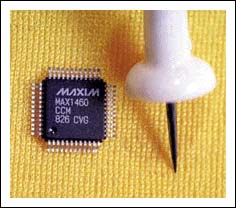
Photo 1. They call it a smart ADC, and the MAX1460 arguably represents Maxim's first entry into the micro market.
Figure 1 gives you a backstage look. The on-chip processor is one link in a signal chain that includes a programmable gain amp, 16-bit ADC, temperature sensor, 12-bit DAC, and op-amp.
Figure 1. The MAX1460 combines everything needed to accommodate a variety of bridge-type sensors. Major integrated functions include a programmable gain amp (PGA), 16-bit ADC, temp sensor, and 16-bit processor.
The micro is described as a RISC or DSP, presumably combining aspects of both (not that there's much difference anymore). At this point, the details of the architecture and on-chip ROM code haven't been disclosed, although much can be inferred by the functions they perform. Piezo De ResistanceTo get a better idea of ​​what the MAX1460 is, let's look at where it came from and what it's supposed to do. The MAX1460 is designed to act as a signal-conditioning front end for a variety of sensors, especially those based on the classic Wheatstone bridge.
The Wheatstone-bridge concept exploits the fact that physical energy (tension or compression) causes a change in resistance detected as a voltage differential between the two legs of the bridge. The Wheatstone bridge is versatile. Use gravity as the physical input and you've got a scale. Turn it sideways and it's an accelerometer. Mechanically connect it, and voilà , a strain gauge. Use the bridge as a diaphragm and it detects pressure, level, and flow.
That's the good news. The bad news is extremely low-level output that is hard to detect and easily swamped by ambient electrical interference. A typical piezo-resistive bridge sensor may be able to generate only 20mV or so per volt of excitation. In a 5V system, that means the peak output is 100mV, which even at meager 8-bit resolution requires the ability to detect low-level signals down to hundreds of microvolts per least-significant bit. Push for 12-bits and you're talking nanovolts !
Resistors also react to temperature (ie, thermistor), which is nice when that's what you want to do. Otherwise, it's a pain. An uncompensated sensor may exhibit thermal errors on the order of 10, 20, or even 30% of full- scale output (FSO) including significant (eg, 5% FSO) nonlinearity. Without temperature compensation, there's no need to worry about A / D resolution because even a few bits of accuracy will be tough to obtain. You know the drill. Get some op -amps, a temp sensor (to compensate), ADC, MCU, and a grab bag of discretes, then have at it. Amplify the input and remove any offset, compensate (both gain and offset) for temperature, and output the digital result .
Earlier parts like the MAX1457 and '58 (see Figure 2), put together a few parts of the puzzle. The main difference is that the '57 uses a relatively large (128 '16) external EEPROM to store temperature compensation coefficients and the' 58 has a smaller EEPROM (8 '16) on chip.
Figure 2a.
Figure 2b.
Figure 2. Earlier Maxim parts, the MAX1457 (a) and MAX1458 (b), targeted the same bridge sensor applications but required support from an external ADC and micro.
The different size of the EEPROM reflects a fundamental difference in the '57's and' 58's approach to compensation. It starts by realizing that the goal of compensation is to come up with curves that cancel the sensor's output and offset thermal error curves. Every programmer knows there are two ways to generate a curve. Either come up with an equation that defines the curve, or use a table lookup. That's the difference between the '57 and '58.
The '57 relies on its larger EEPROM to store a table of output and offset compensations corresponding with up to 120 temperature points. This setup enables the output to be fine-tuned across the entire temperature range, yielding excellent 0.1% accuracy. Meanwhile, the '58 (essentially an analog computer hardwired to execute one calculation) uses an equation incorporating error coefficients. An equation of only a few terms takes up a lot less room in memory than a table, hence the '58's smaller EEPROM. But, a simple equation usually does not perfectly fit a real-world curve, so the '58's accuracy (1%) isn't as good as the' 57's. Still, 1% is good compared to the 10-20% or greater error of an uncompensated sensor.
Although a big improvement over rolling your own, the '57 and '58 are still analog from the system designer's point of view. Not only do you have to come up with an ADC and the software to babysit it, you're likely to encounter problems getting the analog signal from here to there, especially in a high-temperature or otherwise harsh environments where the sensor and controller are physically separated.
Little Signal, Bit BitsEnter the MAX1460. By adding the ADC and micro, the '1460 puts everything under one roof, inputting a tiny signal from the bridge and outputting accurate (0.1%, 12-bit) 1s and 0s. The operating principle is exactly the same as before, but now most of the details and sensitive analog signals are handled on chip.
The design is ratiometric (ie, relative to supply voltage) with input centered around a virtual ground, obtained by connecting 10kW pull-up and pull-down resistors to AGND. Maxim recommends avoiding the extremes of the input range for best signal-to- noise ratio (SNR). So, it's best to try to keep the input between 1 and 4V rather than the full-scale 0-5V.
The first step is coarse amplification ('46, '61, '77, or '93) and offset correction (eight selections) to get dynamic range into the ballpark. The output is a differential voltage between -VDD and + VDD that, post -A / D conversion, is interpreted as an integer value between -32768 and +32767 or, for correction coefficients, a fraction between -1.0 and +0.99997. Once digitized by the 16-bit ADC, the coarse-adjusted input and on- chip temperature-sensor reading are fed to the processor. Although the output is only 12-bits, 16-bits of resolution are required here to prevent quantization and rounding errors from polluting the final output.
The other set of processor inputs comes from the correction-coefficient registers in Table 1 that reflect the offset and output specs for a particular sensor, including thermal characteristics.
Table 1. The key calculation performed by the on-chip processor compensates sensor offset and gain temperature by using sensor-dependent correction coefficients.
Coefficient | Register Address | Function | Range | Format |
Gain | 1 | Gain Correction | -32,768 to +32,767 | Integer |
G1 | 2 | Linear TC Gain | -1.0 to +0.99997 | Fraction |
G2 | 3 | Quadratic TC Gain | -1.0 to +0.99997 | Fraction |
Of0 | 4 | Offset Correction | -1.0 to +0.99997 | Fraction |
Of1 | 5 | Linear TC Offset | -1.0 to +0.99997 | Fraction |
Of2 | 6 | Quadratic TC Offset | -1.0 to +0.99997 | Fraction |
DOFF | 7 | Output Midscale Pedastal | -32,768 to +32,767 | Integer |
With digitized input and temp and the correction coefficients in hand, the processor executes Output = Gain (1+ G1T + G2T2) (Signal + Of0 + Of1T + Of2T2) + DOFF to generate an output that compensates the sensor's offset and gain (see Figure 3).
 |  |
Figure 3. Once calibrated, the output accuracy across temperature of the MAX1460 + sensor pair (a) is dramatically improved compared to the uncompensated sensor (b).
Gain and DOFF deal with the basic gain and offset of the sensor and G1, G2, Of1, and Of2 handle linear and nonlinear components of thermal compensation. Essentially, the MAX1460 processor does in software what the earlier parts did with analog circuits. Once the calculation is complete, the 12-bit result is output in parallel on the D0? D11 pins. It's simultaneously delivered as a bitstream on the OUT pin. Feeding OUT back through the spare on-chip op-amp and adding a few discretes permits a high-level (rail-to-rail) analog voltage or 4-20mA output to be generated.
It may seem odd for a sensor to go both ways (ie, analog and digital outputs), but often, industrial designers require legacy analog capability to help smooth the migration of their customers and installed equipment base to fully digital designs. From the system designer's perspective, MAX1460 operation is simple. Just power up and the signal is acquired and processed, and 67ms later the outputs (D0-D11, OUT) are updated and the EOC pin signals completion. Two chip-select pins (CS1 and CS2) condition all digital I / Os, so multiple '1460s can reside on a common bus.
Conversion can also be initiated with the START pin. This feature is useful if the default 35ms sensor warm-up time is insufficient. There's a repeat mode that automatically reinitiates conversion (max. Sample rate is 15Hz).
Serial SetupUsing the MAX1460 is easy. But, setting it up (ie, determining the proper calibration coefficients and programming them into the on-chip EEPROM) is another story. With the TEST pin asserted, two other pins (SDIO and SDO) provide access to the chip's inner workings. The first gotcha is that in Test mode, the host system is responsible for providing a 2MHz 50% duty-cycle clock on XIN that not only clocks transfers on SDIO and SDO but also runs the chip. According to the designers, the clock could probably range from about 1 to 3MHz before it impacts conversion accuracy, but the data sheet says 2MHz, period.
Calibration for a particular MAX1460 and sensor pair involves determining the appropriate values ​​for the configuration and correction-coefficient registers. The idea is to operate the sensor and MAX1460 pair under various temperature (low, medium, and high) and input-excitation (low and high) conditions to gather enough data points to fit a curve using the output equation and correction coefficients.
To communicate with the chip, the host system issues commands (see Table 2) and monitors processor activity and results via SDIO and SDO. The processor reveals the contents of the accumulator (S), the 8-bit program counter (P), and the 8-bit instruction it's currently executing (PS). A new instruction and corresponding 32-bits of status (S, P, and PS) are delivered every 16 clock cycles.
Table 2. Calibration and EEPROM programming is carried out by a host system that issues commands to the on-chip processor and monitors operation via the SDIO and SDO pins.
Command Hex Code |
| Write a calibration coefficient into a DSP register 1 hex |
| Block-erase the entire EEPROM (write 0 to all 128-bits) 4 hex |
| Write 1 to a single EEPROM bit 2 hex |
| NOOP (no operation) 0 hex |
| Start conversion: registers are not updated with EEPROM 8 hex |
| values. SDIO and SDO are enabled as DSP outputs |
| Start conversion: registers are updated with EEPROM A hex |
| values. SDIO and SDO are enabled as DSP outputs |
| Start conversion: registers are not updated with EEPROM C hex |
| values. SDIO and SDO are disabled |
| Start conversion: registers are updated with EEPROM E hex |
| values. SDIOand SDO are disabled |
| Reserved 3, 5, 6, 7, 9, |
| B, D, F hex |
After issuing the start-conversion command, the host looks for the appearance of certain opcodes on SDIO to catch the conversion result on SDO exactly 130,586 XIN clock cycles later (ie, 65.293ms). Remember that all of this happens at 2MHz.
Once the sensor-specific configuration and calibration is determined, it's time to burn it into the 128-bit (8 '16) EEPROM. This exercise calls for a different (125kHz) clock and multiple commands to program each bit individually. I don' t see any commands to read the EEPROM; only one to erase it. Not sure how comfortable I am with the concept of a write-only memory. On the other hand, it offers security to anyone worried about having their coefficients ripped off. I suspect there's a way to read the EEPROM, but it's not in the data sheet.
Once programmed and put back into service (TEST deasserted), things get simple again. After powerup, the MAX1460 automatically loads the EEPROM contents into the configuration and correction-coefficient registers and does its thing.
EV Way OutThe fact that the setup procedure is nontrivial would seem to dampen aspirations for self-calibrating designs that could adapt over time, perhaps to compensate for sensor aging or environmental changes. To their credit, Maxim appears to disclose enough details to enable you to support in-system self-reconfiguration. But, they clearly expect that reprogramming the EEPROM won't be done often and will be handled by a test system rather than logic built into the application. To that end, they offer the MAX1460 evaluation kit. It includes an EV board with the '1460 and sample pressure sensor, an interface board that connects to a PC parallel port, Windows software that walks the user through calibration, and EEPROM programming and documentation.
Keep in mind that calibration for a custom-matched MAX1460 and sensor pair is tedious. It may take a couple hours because the sensor has to soak for about 30 min. At each temperature. Thus, the software assist that Maxim provides to automate the process is a welcome addition.
Although it's targeted at a fairly narrow niche, I find the MAX1460 intriguing in its implications for the bigger picture. It provides more evidence of the trend towards mixed-signal micros and smart sensors. The Maxim folks I spoke with indicated that opportunities related to IEEE 1451.2 (the digital sensor interface discussed in INK 104) are under review.
Finally, Maxim's entry into the micro marketplace, albeit rather indirectly, may portend exciting times for MCU customers and competitors.
A similar version of this article appeared in the April 1999 issue of CircuitCellar magazine.
Spin dryers are very common in every family. Banshen spin dryers, with high quality, good design and best service. Many products have been sold to over 30 countries. After many years of developing, banshen spin dryers are getting better and better.
Our well-equipped facilities and excellent quality control throughout all stages of production enable us to guarantee total customer satisfaction. Besides, we have received CE, CB, RoHS and CCC certifications.
As a result of our high quality products and outstanding customer service, we have gained a global sales network reaching America, Asia, Europe, Africa, the Middle East and other countries and regions.
If you are interested in any of our products or would like to discuss a custom order, please feel free to contact us. We are looking forward to forming successful business relationships with new clients around the world in the near future.
Big Capacity Spin Dryer,Top Loading Clothes Dryer,Top Load Washer And Dryer,6.5Kg Top Loading Spin Dryer
Ningbo Banshen Electric Appliance Co., Ltd , https://www.banshendq.com