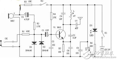
FM FM transmitter, transmitting frequency in the analog broadcast band 88~108Mhz, received by ordinary FM radio, 2 kinds of audio input, MIC head will send peripheral sound, CK audio input, adjust adjustable transmit coil L can change (fine tuning) launch frequency.
As shown in the figure, the schematic diagram of the wireless transmitter is shown in the figure. Q1 is a common-emitter transformer-coupled oscillating circuit: the load is the è¡©-stage coil of the transformer T. After the collector output signal is coupled by T, the secondary pole is sent to the base via C1 to form a positive Feedback, start up. The base is simultaneously supplied with a low frequency modulation signal to amplitude modulate the generated high frequency oscillation.

Q2 is the buffer amplifier stage. The output of Q1 is coupled to the base of Q2 ("Q1" on the right side of the figure) via C3. L1 is the load inductance of Q2; and is sent to the antenna for transmission via the C4/L2 series resonant circuit. R2 is grounded, that is, zero-biased. Because the input signal has a large amplitude and is selected by the C4/L2 resonant circuit, it is not afraid of distortion, so the efficiency is high.
There should be a connection point at T, L1 and 9V. This circuit works in Class C amplification because the base has no DC offset. The phase between the primary and secondary of T is reversed, that is, when the collector current of Q1 increases, the primary induced electromotive force of T is right and left negative, and the secondary produces a positive electromotive force with left and right negative, and the charging current for C1 increases. The opposite is true when the collector current is reduced. The frequency is determined by the capacity of C1 and the inductance of T.
Transmitting power Now these parameters cannot be determined. The voltage knows that the key is that the current is unknown. The current (AC current) is determined by the current of Q2 (the rear transistor should be Q2), the driving of the base, and the impedance of L1.
Speaking of the receiving distance, and the receiver sensitivity, propagation environment, antenna height, antenna gain, generally speaking is also the ideal distance, the actual distance is still a big difference.
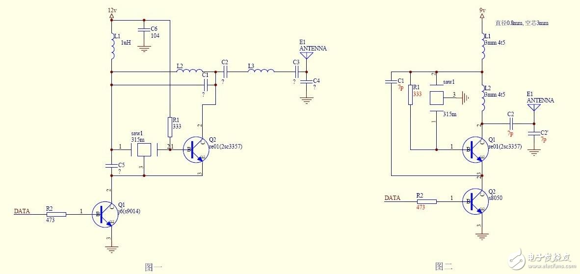
The basic principle of the two circuits is the same, and the circuit is controlled by the 0 and 1 signals to realize the high-frequency pulse emission. The working frequency is determined by the crystal oscillator, and the stability is not good or bad. Figure 2 is simple and easy to debug. Figure 1 adds a frequency-selective network between the collector and the power supply of the triode. A frequency-selective network is added between the collector and the antenna of the triode. The output frequency is purer, but debugging is more troublesome. . Another difference is that the base of the upper triode in Figure 2 introduces AC negative feedback through the resistor. In fact, the effect on the stability of the circuit is not obvious. The high frequency capacitance to ground on the power supply is still good, but it is not shown in Figure 2.
We have experience and skill to support customers to tooling for their required waterproof connectors, like IP68 series,micro fit connectors. Etop wire assemblies for various industries have been highly recognized by all the customers and widely used for automobiles, electrical and mechanical, medical industry and electrical equipemnts, etc. Products like, wire harness for car audio, power seat, rear-view mirror, POS ATM, Diesel valve Cover gasket fit, elevator, game machine, medical equipment, computer, etc.
JST Connector,Molex Connector, Multi-Contact Connector, Micro Fit Connectors
ETOP WIREHARNESS LIMITED , https://www.etopwireharness.com