According to statistics from market research institutions, the market value of China's industrial robots reached US$1.3 billion in 2015, and will maintain a 20% annual compound growth (CAGR), reaching US$3.3 billion by 2020.
In 2015, China’s industrial robot sales accounted for 13% of the world's total, and by 2020 it will reach 25%. The beautiful flower purchase of KUKA is probably also a good development momentum for industrial robots.
Industrial robots belong to one kind of intelligent robots. Intelligent robots are developing rapidly. Let's take a look at the three key technologies used in intelligent robots.
First, multi-sensor information fusion
Multi-sensor information fusion technology is a hot research topic in recent years. It combines control theory, signal processing, artificial intelligence, probability and statistics to provide robots with tasks in a variety of complex, dynamic, uncertain and unknown environments. A technical solution.
The key issues of data fusion are model design and fusion algorithms. Data fusion models mainly include functional models, structural models and mathematical models.
The functional model starts from the fusion process and describes the main functions and databases involved in data fusion, as well as the interaction process between the various components of the system during data fusion;
The structural model starts from the composition of data fusion, and describes the software and hardware components of the data fusion system, the related data flow, the human-machine interface between the system and the external environment;
The mathematical model is the algorithm and integrated logic of data fusion. The algorithm mainly includes distribution detection, spatial fusion, attribute fusion, situation assessment and threat estimation algorithm. The following three aspects are introduced separately.
1. Functional model of information fusion
At present, many scholars have proposed the general functional model of information fusion system from different angles. The most authoritative is DFS (Data Integration Expert of C3I Technical Committee (TPC3) under the US Armed Forces Government-Laboratory Joint Committee (JDL). Group) proposed functional model.
The model divides data fusion into three levels. Level 1 is single-source or multi-source processing, mainly digital processing, tracking correlation and correlation; level 2 is a collection of evaluation target estimates, and their relationship to each other to assess the whole situation; level 3 uses a system A priori set of targets to test the assessment.
2. Structural model of information fusion
The structural model of data fusion has a number of different classification methods, one of which is classified according to the extent to which the sensor data has been processed before being sent to the fusion processing center.
Under this classification standard, the fusion structure is divided into sensor-level data fusion, central-level data fusion and hybrid fusion, and the fusion structure can be classified according to the resolution of the data processing process. In this case, the fusion structure is a pixel level, feature level, and decision level fusion.
3. Mathematical model of multi-sensor information fusion
The method of information fusion involves many aspects of theory and technology, such as signal processing, estimation theory, uncertainty theory, pattern recognition, optimization techniques, fuzzy mathematics and neural networks. Currently, these methods are broadly divided into two categories: random class methods and artificial intelligence methods.
Second, navigation and positioning
In the robot system, autonomous navigation is a core technology and a key and difficult problem in the field of robot research. There are four common navigation and positioning methods for autonomous mobile robots.
1, visual navigation and positioning
In the visual navigation and positioning system, the current application at home and abroad is based on local vision, the navigation method of installing the vehicle camera in the robot.
In this navigation mode, the control device and the sensing device are loaded on the robot body, and high-level decisions such as image recognition and path planning are all completed by the vehicle control computer.
The visual navigation positioning system mainly includes: a camera (or CCD image sensor), a video signal digitizing device, a DSP-based fast signal processor, a computer and peripherals thereof.
There are many robot systems that use CCD image sensors. The basic component is a row of silicon imaging elements. Photosensors and charge transfer devices are arranged on a substrate. The video signals of multiple pixels are time-sharing and sequential by the sequential transfer of charges. Take out the image, such as the image acquired by the area CCD sensor, the resolution can be from 32 & TImes; 32 to 1024 & TImes; 1024 pixels.
The working principle of the visual navigation and positioning system is simply to optically process the environment around the robot. The camera first collects the image information, compresses the collected information, and then feeds it back to a neural network and statistical methods. The learning subsystem, and then the learning subsystem associates the acquired image information with the actual position of the robot to complete the autonomous navigation and positioning function of the robot.
2, light reflection navigation positioning
A typical light reflection navigation positioning method mainly uses a laser or an infrared sensor to measure distance. Both laser and infrared use light reflection technology for navigation and positioning. The laser global positioning system generally consists of a laser rotating mechanism, a mirror, a photoelectric receiving device, and a data acquisition and transmission device.
During operation, the laser is emitted outward through the rotating mirror mechanism. When scanning the cooperative road sign formed by the retroreflector, the reflected light is processed by the photoelectric receiving device as a detection signal, and the data acquisition program is started to read the code wheel data of the rotating mechanism ( The measured angle value of the target is transmitted to the host computer for communication through communication. According to the position of the known road sign and the detected information, the position and direction of the sensor under the landmark coordinate system can be calculated to achieve further navigation. The purpose of positioning. The figure is a block diagram of an LDSR laser sensor system. Laser ranging has the advantages of narrow beam, good parallelism, small scattering, high resolution in the ranging direction, but it is also greatly interfered by environmental factors. Therefore, how to denoise the collected signal when using laser ranging is also a Bigger problems.
In addition, there is also a blind spot in laser ranging. Therefore, it is difficult to achieve navigation by laser. In industrial applications, it is generally used in industrial field detection within a certain range, such as detecting pipeline cracks.
Infrared sensing technology is often used in multi-joint robotic obstacle avoidance systems to form a large-area robot "sensitive skin" that covers the surface of the robot arm and can detect various objects encountered during the operation of the robot arm. The typical infrared sensor works as shown.
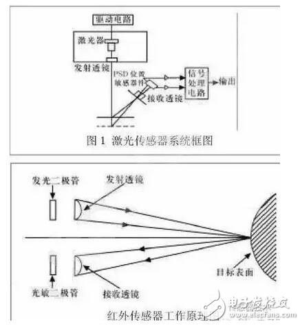
The sensor includes a solid state light emitting diode that emits infrared light and a solid state photodiode that acts as a receiver.
The modulated signal is emitted by the infrared light-emitting tube, and the infrared photosensitive tube receives the infrared modulated signal reflected by the target object, and the elimination of the ambient infrared light interference is ensured by the signal modulation and the dedicated infrared filter.
Let the output signal Vo represent the voltage output of the reflected light intensity, then Vo is a function of the distance from the probe to the workpiece:
Vo=f(x,p) where p is the reflection coefficient of the workpiece. p is related to the surface color and roughness of the target. X—the distance from the probe to the workpiece. When the workpiece is a similar target with the same p value, x and Vo correspond one-to-one. x can be obtained by interpolation of experimental data of proximity measurement of various targets.
In this way, the position of the robot from the target object can be measured by the infrared sensor, and the mobile robot can be navigated and positioned by other information processing methods. Although infrared sensing positioning also has the advantages of high sensitivity, simple structure, low cost, etc., because of their high angular resolution and low range resolution, it is often used as a proximity sensor in mobile robots to detect adjacent or sudden motion. Obstacle, easy robotic emergency stop.
3, GPS global positioning system
Nowadays, in the application of navigation and positioning technology of intelligent robots, pseudo-distance differential dynamic positioning method is generally used. The reference receiver and the dynamic receiver jointly observe 4 GPS satellites, and according to a certain algorithm, the robot can be obtained at a certain moment. Three-dimensional position coordinates.
Differential dynamic positioning eliminates the star clock error. For users 1000km away from the base station, the star clock error and the tropospheric error can be eliminated, which can significantly improve the dynamic positioning accuracy.
However, in mobile navigation, the positioning accuracy of mobile GPS receivers is affected by satellite signal conditions and road environment, and is also affected by many factors such as clock error, propagation error, and receiver noise.
Therefore, the use of GPS navigation alone has a problem of low positioning accuracy and low reliability. Therefore, in the navigation application of the robot, the data of the magnetic compass, the optical code disc and the GPS are usually used for navigation.
In addition, GPS navigation systems are not suitable for use in indoor or underwater robot navigation and for robotic systems where position accuracy is high.
Wireless Charging Multifunctional Sterilizer
Phone Sterilizer,Mobile Phone Sterilizer Box,Wireless Charging Uv Sterilizer Box,Wireless Charging Multifunctional Sterilizer
wzc , https://www.dg-wzc.com