1 Introduction
At present, schools of a certain scale all have a network-based campus consumption information management system. To establish a stable and reliable system that is easy to expand and maintain, the key is to establish an information transmission network suitable for the campus consumption environment. At present, the underlying network of campus consumer information management system mostly adopts the networking mode of RS-485 bus. The use of RS-485 bus networking has the advantages of simple structure and low cost, but the RS-485 bus has no fault location and error handling functions, and the flexibility of networking is not strong. With the increasing popularity of the Internet, there are also some campus consumption information management systems in schools that use Ethernet networking to connect each consumer node to the campus network. The characteristic of this networking method is that it can make full use of the existing network resources and can facilitate remote access, but under the current situation, the disadvantage of this method is that the networking cost is higher, the real-time response ability is not strong, and the network is completely Rely on the campus network, and the campus network does not guarantee safety and reliability. Of course, the Internet has tremendous advantages and application prospects, but in terms of the underlying network of the campus consumer information management system with a small amount of transmitted information and high real-time requirements, Ethernet is not the best choice.
This paper presents a low-level network design scheme for a campus consumer information management system based on CAN network controllers with relatively high performance and price. The CAN bus has outstanding characteristics such as high transmission rate, strong anti-interference ability, and convenient hardware connection. It has been widely used in smart cars, distributed information collection and control, etc. The CAN bus is used in the design of the underlying network of the campus consumer information management system. Its networking cost is equivalent to that of the RS-485 bus, and its use, maintenance, and expansion are more convenient. Compared with Ethernet, it has the advantages of low price, good real-time performance and high reliability. For more information, please log in to the electronic enthusiast website (http: //)
2 CAN network controller
Due to the large campus area of ​​many schools and the scattered consumption points, there is a need for a network device to connect each consumption point with a server to achieve efficient and real-time transmission of consumption information. Such network equipment generally uses repeaters, and this paper proposes a solution using a CAN network controller. The CAN network controller designed in the system not only has the relay function, but more importantly, it makes full use of the flexible configuration of the CAN bus controller, and realizes the filtering of messages between the two CAN subnets, so that each The subnets can all operate efficiently, and these are transparent to each CAN node and server. Therefore, the CAN network controller is a key device for the networking of campus consumer information management systems. It can increase the flexibility of network design and greatly expand its scope of use. The CAN network controller is composed of a microprocessor and two CAN controller interfaces. There is E2PROM in the network controller, which is used to save the configuration parameters and other information of the network controller. Due to the real-time requirements of communication and the limited internal cache capacity of the microprocessor used by the CAN network controller, the microprocessor uses a FIFO mechanism to manage the internal RAM and improve the efficiency of memory usage.
3 Campus consumption information management system network design
3.1 Campus consumption information management system network structure
The main body of the campus consumer information management system network is composed of three parts: the consumer information management center server, CAN network controller, and network terminals (including window machine, recharge machine, and lost machine, etc.). Among them, the CAN network controller is the core device of the network. The campus consumption information management system based on CAN network controller has been successfully applied in a university. Its network structure is shown in Figure 1. It can be seen from the figure that the network controller connects terminals such as window machines to the server. In this network structure, the network controller is divided into two levels. One end of the first-level network controller is connected to the server, and the other end is connected to a subnet formed by terminals such as window machines at various consumer sites. The first-level network controllers are all located in the consumer information management center. This method provides convenience for management and maintenance. On the other hand, the first-level network controllers are very close to the server and can use up to 320Kbps. Communication rate. The network controller 5 in the figure is a secondary network controller. The design of two-level network controller makes the communication distance of the system up to 5km and the number of network terminals is almost unlimited.
In order to improve the reliability of the network, each CAN node in the system is coupled with a photoelectric coupler, which can effectively isolate the fault and protect the safety of the network equipment. In order to improve the maintainability of the network, you can make full use of the ability of the CAN bus in error control and fault handling, and adopt the method of the server periodically querying the current status of each network device, so that the server can keep abreast of the current operation of the entire network in time, which is better for Management and maintenance, it can also be used to locate the fault when the network fails, and eliminate the fault in time.
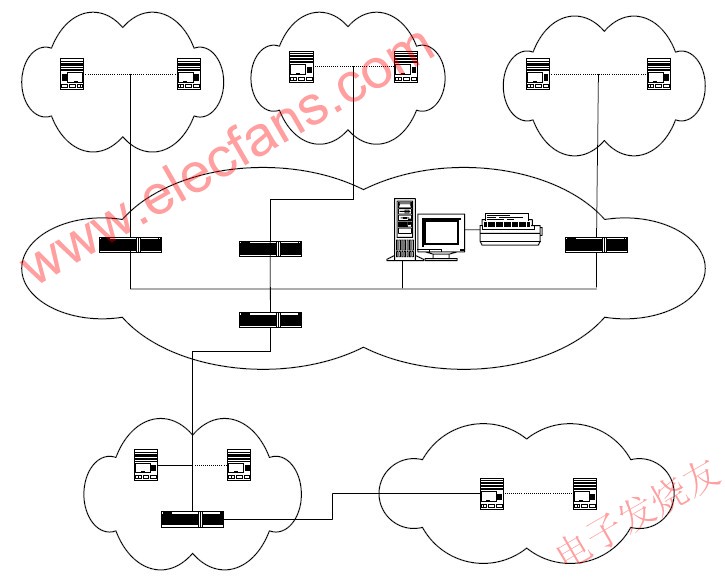
Figure 1 Network structure of campus consumption information management system
3.2 Network configuration of campus consumption information management system
Many functions of the campus consumer information management system network are realized through the configuration of the network communication parameters of each CAN communication node. This configuration is somewhat similar to the allocation of Ethernet IP addresses. The parameter configuration of each network device in the system includes the allocation of identifier (ID), acceptance mask register (AMR), acceptance code register (ACR) and baud rate (BTR) and other parameter settings. The network equipment can be configured automatically by the server. All configured parameters are saved in the server's database.
As shown in Fig. 2, in the parameter configuration of the system network equipment, an important consideration is the assignment of identifiers. In this system, only 21 bits of the 29-bit identifier of the CAN bus are used, and the upper 8 bits are used as command bytes during communication. Due to the uniqueness of the identifiers in a network, the allocation of 21-bit identifiers must be uniformly assigned by the server according to the different subnets where the network devices are located, in addition to the acceptance mask register (AMR), acceptance code register (ACR), and baud rate (BTR ) And other parameters are also related to the subnet.
Table 1 21-bit identifier assignment

The 21-bit identifier is divided into 4 segments, which are allocated according to the segmentation method in Table 1. The specific ID allocation of each network device is shown in Figure 2. The server is located on the trunk, one end of the first-level network controller is connected to the trunk, and the other end is connected to the subnet. Both network controller 1 and network controller 2 are first-level network controllers. The network controller 3 is a second-level network controller. The second-level network controller is connected to a subnet formed by the first-level network controller, and at the same time, a terminal such as a window machine or a lost machine is also connected to the subnet. The system uses a two-level network structure.
The configuration of AMR and ACR is coordinated with the ID of the device. The specific configuration is shown in Figure 2. In this system, the server, network controller and terminal all use the single filter mode of the extended frame. With the configuration shown in Figure 2, the information sent by the window machine will only be forwarded to the server by the network controller, but not to other subnets, and the information sent by the server to the window machine will only be forwarded by the network controller to the window. In the subnet where the machine is located, it has the function of packet filtering. The configuration of the baud rate (BTR) is not mentioned in Figure 2. It is also a parameter that needs to be configured, and the baud rate parameter of the device and the connected network should be consistent.
There is a corresponding database and operation interface in the server to realize the configuration function of the above parameters. During configuration, the device type and service area are selected through the interface, and the server generates configuration information according to the relevant rules and the information stored in the database Automatic configuration.
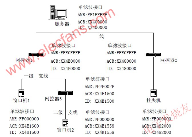
Figure 2 Network parameter configuration diagram
3.3 Network performance analysis of campus consumer information management system
The network designed with the above network structure and parameter configuration method fully utilizes the characteristics of the CAN bus and can fully meet the requirements of the campus consumer information management system for network bandwidth and real-time performance. As shown in Figure 1, because the distance between the first-level network controller and the server is very close, the communication rate of the main line connected to the server can reach 320Kbps or even higher, so that the advantage of CAN bus communication speed is fully brought into play.
During the network design process, the real-time response capability was repeatedly simulated. The test environment was as follows: The server used a PIV 2GHz HP computer, the programming language was Delphi, and the main line speed was 320Kbps. The three network controllers were connected to three Window machine, the speed is 80Kbps, 80Kbps and 40Kbps respectively. The three window machines work at full speed to simulate consumption. When the server's response database uses the Delphi local database, the response times can be as high as 120 times / s, and when the database is SQL Server 2000, the response times are reduced to 60 times / s or so. In the same network environment, the real-time response capability of the system varies greatly, and this is mainly related to the response speed of the server. This can be more clearly understood through the following analysis.
Each normal consumption process includes a total of 4 frames of data, and the total communication volume is about 500 bits. According to the response times of 60 times / s, the required bandwidth is 30Kbps, which is far less than 320Kbps. Therefore, the main factor affecting the number of responses is not the network bandwidth, but the server's responsiveness. Under the existing bandwidth of 320Kbps, it can fully meet the network communication requirements of 200 consumptions / s. In order to increase the number of responses, the server's calculation speed should be increased and the software design should be optimized.
The response times mentioned above are only the average system responsiveness, but the specific response time (TR) that each window machine can best reflect its real-time response performance is the response time from the window machine to the server. The time elapsed after receiving the server's response data. This period of time consists of two parts: the network delay (Tn) and the server's processing delay (Tp).
TR = Tn + Tp (1)
It is difficult to discuss the size of Tp in a strict sense, and its average value can be roughly measured by the number of responses per second of the server. The Tp value is the same for each window machine, so the difference in real-time response performance of different window machines is mainly due to the difference in Tn. K. TIndell analyzed the delay characteristics of the CAN bus system in the worst case in his article. The CAN bus system model discussed in this article is simpler. As shown in Figure 1, the number of window machines in the new canteen is the largest, with a total of 40 units, so the possible network delay is also the largest.
The time (Rm) required by the window machine m from sending a request to receiving data by the server can be expressed by (2).
Rm = Tm + Cm (2)
In the formula, Tm refers to the time required to send a frame of data, and Cm refers to the time required for the window machine m to compete for the bus. The size of Cm mainly depends on the size of the window machine identifier (ID). The smaller the ID and the higher the priority, the smaller the Rm, and vice versa. In the worst case, the longest delay is the delay of the window machine with the lowest priority (the largest ID) (set to window machine No. 40). Due to the particularity of data transmission in the consumption process, the window machine with the lowest priority generally only needs to wait until all window machines with higher priority send a frame of data, so the size of the window machine in the worst case C40 :
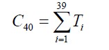 (3)
(3) Suppose the size of each frame of data is 150bit. In the case of a communication rate of 80Kbps, the Rm of window machine 40 in the worst case is about 75ms. If the forwarding delay of the network controller and the contention delay on the trunk are considered, the maximum Rm will not exceed 150ms. The maximum network delay Tn is twice Rm, namely:
Tn = 2Rm≤300ms (4)
If Tp is calculated in 20ms, the response delay TR is 320ms at the maximum. This period of time does not have much impact on the actual use of the window machine, and this is the worst case delay, the probability of its occurrence is very small, so it does not affect the actual use at all.
4 Conclusion
By analyzing the deficiencies of the commonly used campus consumer information management system network, the article introduces a campus consumer information management system network design scheme based on CAN network controller. The article analyzes in detail the network structure and configuration method of the underlying network of the campus consumer information management system formed by the CAN network controller, and discusses network bandwidth and worst-case delay. Through these analyses and discussions, it can be seen that the designed network has the following characteristics:
◠Strong anti-interference ability, long communication distance, up to 3 ~ 5km
â— With automatic configuration and status feedback function, easy to use and maintain
â— With real-time response capability, the maximum response delay does not exceed 320ms
â— The number of connectable network terminals is large, the expansion is convenient, and the cost is low
This network is just a low-cost low-cost network of the campus consumer information management system, and many schools now have multiple campuses, which requires the network to have remote access capabilities. The solution was realized. For more information, please log in to the electronic enthusiast website (http: //)
Automotive Fuse
Automotive Fuse, ie Car Fuse , is the name we are often called. Its official name is "fuse protector." The use of Automotive Fuse Block is very similar to that of household fuses, which act as a circuit protection barrier when the circuit current is abnormal and exceeds its rated current. Vehicle fuses are broadly divided into two types of fast-blow fuses and slow-blow fuses.

A car is made of Car Fuse, Automotive Switches and other kinds of Automotive Accessories, and the Automotive Switches including Automotive Rotary Switches, Automotive Battery Switches, Automotive Rocker Switches

Inline Fuse Holder include high-current fuses and medium-low current fuses. Medium and low current fuses are generally easier to reach. Low-to-medium current fuses can be broadly classified as chip fuses (including automatic fuse box mini-fuse), plug-in fuses, screw-on fuses, and tube fuse box fuses. Among them, we are able to access medium-sized ATO or small-size fast-acting chip fuses. Chip fuses can carry small currents, short pulse currents, such as headlamp circuits, post-glass defrosting, and more.
Automotive Fuse
Car Fuse,Automotive Fuse,Automotive Mini Fuses,Automotive Fuses Types
YESWITCH ELECTRONICS CO., LTD. , https://www.yeswitches.com