1.1 The main objectives and standards of DVB
? DVB (Digital Video BroadcasTIng) means digital video broadcasting. DVB is a project participated by more than 170 organizations in Europe. It includes the broadcasting and transmission of satellite, cable TV and terrestrial broadcast ordinary TV and high-definition TV.
? The main goal of the DVB project is to find a digital TV technology and system that is suitable for all transmission media. The requirements for it are:
(1) The system should be able to flexibly transmit MPEG-2 video, audio and other data signals.
(2) The system uses a unified MPEG-2 transport bit stream multiplex.
(3) The system uses a unified service information system to provide details such as broadcast programs.
(4) The system uses a unified first-level Reed-Solomon forward error correction system.
(5) Use a unified scrambling system, but may have different encryption.
(6) Select the modulation method and channel coding method suitable for different transmission media and any necessary additional error correction methods.
(7) Encourage the use of DVB standards outside Europe to promote the establishment of worldwide digital video broadcasting standards. This goal is supported by ITU satellite broadcasting.
(8) Support the teletext system in the digital system.
There are three main standards: DVB-S, DVB-C and DVB-T, which are used for satellite, cable TV and terrestrial broadcasting, respectively, and have been approved by ETS (European TelecommunicaTIon standard). DVB-S has been recommended by ITU. The standard of DVB-S is ETS300421, the standard of DVB-C is ETS300429, and the standard of DVB-T is ETS300. ?
1.2 Main technologies used by DVB system
? The core technology of various DVB systems is universal MPEG-2 video and audio encoding. At present, MP @ ML is mainly used in digital satellite and cable TV broadcasting. Therefore, the first-generation European DVB receiver will provide images up to "625-line studio quality" (ITU-R Rec.BT 601), which can be 4: 3 or 16: 9 aspect ratio. The bit rate used can also be determined according to business requirements. Generally speaking, the higher the selected bit rate, the better the image quality, but the wider the occupied frequency band. The choice of bit rate has a lot to do with the content of the image. For images with more sports such as sports programs, a larger bit rate should be used; for programs such as cartoons, a lower bit rate can be used. Therefore, at present, when multiple program bit streams are multiplexed into one bit stream, statistical multiplexing is adopted, which can flexibly allocate the total bit rate among programs with different bit rates. In order to meet the requirements of all kinds of materials, the digital rate required for IT U-Rec? TB 601 studio quality is 9Mbps, and the digital rate required for PAL / SECAM broadcast quality is 5Mbps, because the MPEG-2 transmission bit stream is a data packet Structure, so you can easily add appropriate information, combine a variety of different services, such as image sound and data services, and make detailed regulations on the format of service information. The resulting standard is the service information standard ETS300468. Also because MPEG-2 has not determined the actual scrambling system and key management system, DVB has developed a conditional access public interface for decoder applications.
1.3 DVB-S system
? DVB-S system can be applied to a variety of satellite broadcasting systems, satellite transponder bandwidth can be from 26MHz to 72MHz. Transponder power from 49dBW to 61dBW.
? The signal processing of the sending end is divided into the following levels:
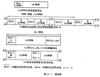
? First of all, MPEG-2 source coding and multiplexing, encoding the input video signal, audio signal and data according to MPEG-2 format, and then forming a useful data packet format through program multiplexing and transmission multiplexing, the packet length is 188 Special, including 1 simultaneous bet.
? Then stream this data code through multiple processing. Its purpose is to increase the signal's resistance to bit errors and adapt it to the transmission characteristics of the channel. These processes include: randomizing the data with a pseudo-random sequence, using Reed-Solomon coding RS (204, 188 T = 8) and convolutional interleaving coding techniques to increase the resistance to bit errors.
? Finally sent to the transponder with QPSK modulation.
? The frame structure of DVB-S is shown in Figure 13-1. In order to achieve maximum power utilization without greatly reducing spectrum utilization, the satellite system is best to use QPSK modulation and use convolutional codes and RS concatenated error correction, which can achieve better results. This system is best used in a system with one transponder and one carrier, and can be used in a multi-carrier system.
 1.4 DVB-C system
The cable TV system can be represented by the block diagram of Figure 13-2, which is divided into two parts: CATV front end and integrated decoding receiver (IRD, also known as integrated decoding receiver). In order to make the various transmission methods as compatible as possible, most of the processing except channel modulation is the same as the processing in satellites, that is, they have the same pseudo-random sequence scrambling code, the same RS error correction, and the same convolutional interleaving. The subsequent processing is specifically for cable TV. First perform the conversion from Beit to symbols. For example, 64QAM converts 8-bit data into 6-bit symbols, and then differentially encodes the first two bits and then converts the remaining 4 bits into corresponding points in the constellation diagram. The scheme can be adapted to three modulation modes of 16, 32, and 64QAM. Table 13-1 is an example of the application rate of CA TV using DVB-C standard.
? DVB standards for cable TV include:
· ETS300468——Channel coding and modulation in cable systems;
· ETS300472——B-text teletext transmission in ITU-R;
· ETS300473——channel coding and modulation in SMATV system;
· ETS300743——DVB ​​real-time subtitle system;
· ETR154——Guide to the realization of MPEG-2;
· ETR162——SI code position;
· ETR211——Guide to realize the role of SI;
? ETR289-shared scrambling;
· EN50083——Interface of transport stream and wired front end. ?
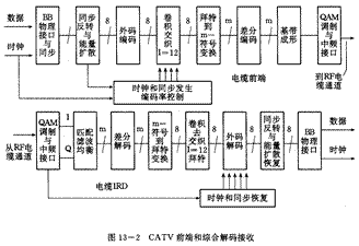
Table 13-1 Application Examples of DVB-C in CATV Network
| Useful bit rate Ru? MPEG-2 TS | Total bit rate Ru including RS? (Mbps) | Symbol rate ?? (Mbaud) | Occupied bandwidth? | Modulation method |
| 38.1 31.9 25.2 | 41.34 34.61 27.34 | 6.89 6.92 6.84 | 7.92 7.96 7.86 | 64-QAM 32.QAM 16-QAM |
| 31.672PDH | 34.367 | 6.87 | 7.90 | 32-QAM |
| 18.9 16.0 12.8 | 20.52 17.40 13.92 | 3.42 3.48 3.48 | 3.93 4.00 4.00 | 64-QAM 32-QAM 16-QAM |
| 9.6 8.0 6.4 | 10.44 8.70 6.96 | 1.74 1.74 1.74 | 2.00 2.00 2.00 | 64-QAM 32-QAM 16-QAM |
2 MCNS standard?
2.1 MCNS standard system
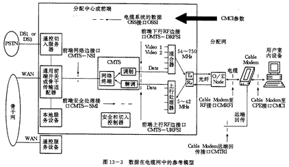
? MCNS is the abbreviation of "MulTImedia Cable Network System", which means multimedia cable network system. The MCN S standard has become the standard for digital cable television systems in the United States and has become the basis of international standards. MCNS is suitable for optical fiber-cable network, namely HFC network. MCNS gives a reference model for data transmission in the cable network. According to this model, each interface interface and the technical requirements for each interface are specified. Therefore, set-top boxes and data modems produced by different manufacturers are allowed to work in the same cable system, with good uniformity and interchangeability.
? The MCNS standard system includes the following
· · SP-CMCI cable Modem to user indoor equipment interface;
· · SP-CMRFI cable Modem to RF interface;
· · SP-CMTRI cable modem telecommunication backhaul interface;
· Downstream RF interface in SP-CMTS-DRFSI cable Modem transmission system;
· · SP-CMTS-NSI cable modem transmission system network side interface;
? · SP-CMTS-SMI cable modem transmission system security management interface;
· Upstream RF side interface in SP-CMTS-URFSI cable Modem transmission system;
· SP-OSSI work support system interface;
• TR-OSSI work support system.
? Among them SP stands for SpecificaTIon namely specification parameter, TR stands for technical report, in order to understand SP content. The usual cable TV system here is renamed as cable modem transmission system, because it transmits various data in addition to the TV signal to distinguish the previous cable TV system. Modem is the modem. ?
2.2 Reference model of data in cable network
? The reference model of the data in the cable network is shown in Figure 13-3. ??
2.3 MCNS technical specifications
(1) The front end is called the cable modem termination system (CMTS).
· Requires suitable MCNS front-end hardware equipment, such as a universal broadband router, using standard Cisco 7200 router and IOS software, which can support MCNS radio frequency and telephone return mode
· Network interface: 10BaseT, 100BaseT, ATM, HSSI.
? (2) Cable Modem (CM)? · Requires client-side hardware equipment suitable for MCNS.
· Interface with PC: Ethernet 10BaseT.
· Interfaces planned: USB and IEEE1394.
? (3) Data protocol: TCP / IP
? (4) Remote management through Simple Network Management Protocol (SNMP)
(5) Downlink according to the requirements of Annex B of ITUJ 83.
? Modulation: 64QAM or 256QAM.
• Maximum data rate: 27Mbps or 38Mbps.
· Bandwidth: 6MHz channel bandwidth, also supports 7MHz and 8MHz.
? Frequency range: 88-860MHz.
• Transmission protocol: MPEG-2. ?
(6) Upstream
? Modulation: 16QAM or QPSK, variable symbol rate.
? Data rate: 320kbps ~ 10Mbps.
· Bandwidth: 200KHz ~ 3 ~ 2MHz.
? Frequency range: 5-42MHz.
• The system is initially set to the highest symbol rate according to the modulation method, and then adjusted to the appropriate rate based on the detected noise level.
· The available speed range and bandwidth used are shown in Table 13-2. ?
Table 13-2
| Uplink symbol rate (Ksps) | QPSK data rate (kbps) | 16QAM data rate (kbps) | Band used (KHz) |
| 160 | 320 | 640 | 200 |
| 320 | 640 | 1280 | 400 |
| 640 | 1280 | 2560 | 800 |
| 1280 | 2560 | 5120 | 1600 |
| 2560 | 5120 | 1024 | 3200 |
3.1 DAVIC system description
? DAVIC is the abbreviation of Digital Audio-Visual Council, that is, the abbreviation of Digital Audio and Video Council, headquartered in Geneva, is a non-profit organization. The purpose is to promote the development of broadcast and interactive digital audio, video applications and services, and to develop end-to-end open interfaces, protocols and regulations that can adapt to various video and audio applications and services and can interoperate across different environments in different countries of the world Including almost all applications and services of digital video and audio, the content is extremely comprehensive and extensive. D AVIC is open to all government agencies, international organizations, companies and individuals. As of December 1995, DAVIC had 202 members in more than 20 countries, including almost all companies and organizations in the world involving digital AV applications and businesses . DAVIC is not a special regulation for the system, but for the use of technology and tools. Because the regulations for the system are often for specific applications, and the DAVIC regulations must not be system-specific, and should be applicable to different industries and systems. The main process of specifying a tool is to analyze the target system first, divide the system into various parts, identify the common parts in the system, make the necessary provisions for each part, and check whether the provisions of the tool are suitable for combining the entire system. As long as it is technically feasible, carry out the repositioning of the movable position of the tool after perfection. DAVIC requires that a tool has only one functional feature and is consistent everywhere, but can have different levels of performance. If specified, general performance can be specified first, but future improvements can be retained to make it backward compatible. You can use Figure 13-4 to briefly describe the DAVIC system. Any DAVIC system can be decomposed into five major parts: content provider system (CPS: Content Provider System), service provider system (SPS: Service Consumer Provider System) and service consumer system (SCS: Service System) and the delivery system between them CPS-SPS delivery system and SPS-SCS delivery system. In principle, DAVIC can define any subsystem in the same way. ??
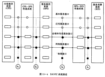
In the analog world, all similar systems are defined by companies or groups of companies independently of each other, because analog systems do not have the flexibility and interconnection as digital systems. The services and applications of analog systems are often closely linked to the delivery system, that is to say, no matter what quality we usually say, TVs always use 8MHz bandwidth channels for transmission, and telephones always use 4kHz dedicated systems for transmission, etc. Multiple devices that cause various businesses. The digital system unifies various services, which requires strict definition and division of labor for the system. In order to ensure the interoperability of various devices and various systems. DAVIC defines many interfaces and layers, such as A11, A10, A9, A1 interfaces and physical layer interfaces, network service interfaces, meeting and transmission service interfaces, application service interfaces and basic service interfaces, etc. Detailed definition of interfaces and levels.
3.2 DAVIC file
• There are 13 parts in DAVIC files, which are divided into two categories. One is official documents, equipment must be observed, and the other is informal. It is currently an informal part but may become official in the future.
? (1) DAVIC system function description.
? (2) System reference mode and scheme.
(3) Service supply system structure and interface.
(4) Transfer system structure and interface.
(5) Service consumption system structure and advanced application program interface.
(6) There is no content reserved for other purposes.
(7) High-level and mid-level agreements, Appendix A: Set-top box management information foundation.
? (8) Low-level protocol and physical interface.
(9) Information presentation, appendix: packaging of personal data.
(10) Confidentiality.
? (11) Use information protocol.
? (12) Reference point.
? (13) Interoperability and compliance. ?
The eighth part 7-7 section of the cable band pass unidirectional physical layer interface (Passband Unidirectional PHY on coax) to look at the connection and difference with DVB-C. This physical layer port supports one-way transmission of wireless frequency bands (up to 1GHz) in the cable, also known as QAM-link on HFC on HFC. This physical layer interface describes the complete physical layer structure, which includes the frame structure, channel coding and modulation method for S1 and S2 information flow packaging. The physical layer and framing regulations are the same for both types of information flow. ??

? Provide two frame structures for downlink data transmission, one is to carry MPEG-2 transport stream packet, and the other is to carry ATM cells. Both structures should be used for RF carriers. The frequency configuration of the cable unidirectional physical layer interface is shown in Figure 13-5. The frequency ranges from 54MHz to 1000MHz, and is divided into QAM modulation channels at 6 or 8MHz intervals.
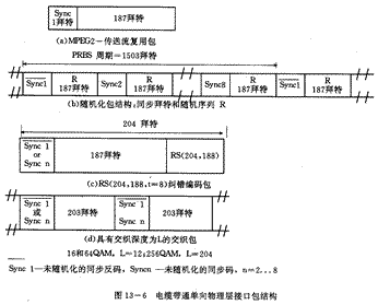
? The set-top box should be able to work within the specified frequency range and support at least one frame structure. The sending device only needs to work within the specified working frequency band. There are three levels of QAM: 16QAM, 32QAM and 256QAM. The codec block diagram is the same as DVB-C. The difference is that DVB-C's QAM uses three levels of 16, 32, and 64, and the interleaving depth is L = 12, while DAVIC uses 16, 64, and 256QAM. It is 12, but for 256QAM, the interleaving depth L = 204. Otherwise, the DAVIC frame structure when using the MPEG-TS stream is exactly the same as DVB-C. It is also flipped synchronously every eight 188 bait packets, and other processing is the same as DVB-C, as shown in Figure 13-6.
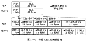
For the transmission of ATM packets, in order to provide interleaved synchronization and alignment error correction code blocks, use the same 188 Beit ATM multiplexed packets as DVB-C. The packet structure is shown in Figure 13-7. It can be seen from the figure. When using the double-packet structure to transmit the frame structure of the ATM, 7 ATM packets with 48 bate information, 5 bate headers, and a total of 53 bates are converted into 2 188 bettes with 187 bate information and 1 bate header. package. ??
DAVIC also provides a tool that improves synchronization reliability and is transparent to the transmission standard "High Reliability Mark"
The DAVIC standard also defines some items and parameters not covered by DVB-C, such as defining two levels of QAM, the first level A, only involving 16 and 64QAM, and the second level B, including 16, 64 and 256QAM.
? From the above, we can see that most of the provisions of DAVIC and DVB-C are the same, but supplemented.
LED Headphones are a time-honored product. It is not a simple headphone, in the strict sense. It is not just a headset that provides a high-quality audio experience, but also a trendy, fun, life-giving and enthusiastic product. The introduction of the LED Headphone will bring fresh blood to the entire headphone market. It is a cross-border digital headphone.
Advantages:
1: Bright colors, dazzling in the night, fashion avant-garde.
2:180° angle illumination. 3.The color of the light is even and delicate, bright and rich.

LED Headphones
LED Headphone,LED Bluetooth Headphones,LED Light Up Headphones,Wireless LED Headphones
Shenzhen Linx Technology Co., Ltd. , https://www.linxheadphone.com