Abstract: The characteristics, components, architecture and development prospects of IEEE802.15.4 protocol are introduced, the IEEE1451 smart sensor model is analyzed, a wireless smart sensor network structure design based on IEEE802.15.4 protocol is proposed, and its implementation is discussed.
In recent years, with the rapid development and wide application of computer technology, network technology and wireless communication technology, people have begun to combine wireless network technology with sensor technology to provide the concept of wireless networked sensors. It can be applied not only to Internet access and interconnection, but also to occasions where the wired access method is not competent to provide high-quality data transmission services. For example, between huge equipment in factories, low-speed and long-distance communication requirements, and dangerous industrial environments.
In December 2000, IEEE established the IEEE802.15.4 working group, devoted to defining a low-rate wireless connection technology with extremely low complexity, cost, and power consumption from inexpensive fixed, portable, or mobile devices. The convenience, flexibility, easy connection, practicality and reliability of the product and its continuity are the driving forces of the market. It is generally believed that short-range wireless low-power communication technology is most suitable for use in sensor networks, which are the main deployment objects of the 802.15.4 standard. Combining sensors with 802.15.4 equipment for data collection, processing, and analysis can determine whether or when user operation is required. Wireless transmitters / receivers and networks that meet the 802.15.4 standard are highly respected by international communications and industrial control giants such as Motorola, Philips, Eaton, Invensys, and Honeywell. At present, the IEEE1451 working group has considered implementing WSN (Wireless Sensor Networks) on its basis. This paper discusses the realization of wireless smart sensor network based on IEEE802.15.4 standard. 
1 Intelligent sensor model based on IEEE802.15.4 standard
1.1 IEEE1451 smart sensor model
Smart sensors establish a standardized sensor network protocol. It stipulates the electronic data form of the sensor module, and also defines the digital interface for accessing the data form, reading the sensor data, and setting parameters. The purpose of IEEE1451 is to provide an industry standard interface to effectively connect sensors and microcontrollers, and connect sensors to the network.
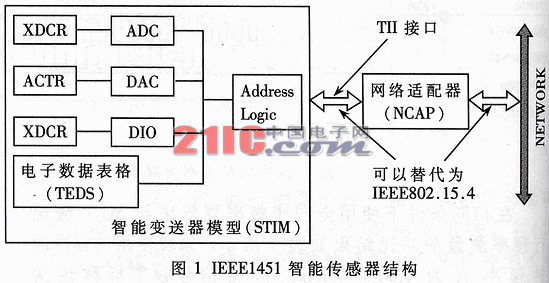
The IEEE1451 model is mainly composed of a smart sensor interface module STIM (Smart Transducer Interface Module) and a network application processor NCAP (Network Capable ApplicaTIon Porcessor), which are connected through a separate sensor interface TII. The NCAP module is used to run the network protocol stack and application hardware, and is interconnected with the network; the STIM module is an intelligent transmitter interface module, which includes the transmitter electronic data sheet TEDS (Transducer Electronic DataSheet). Or actuator, the sensor and STIM are inseparable during normal use. Transmitter independent connection TII (Transducer Independence Interface) mainly defines the point-to-point connection between the two, and the moment distance interface of the synchronized clock, so that manufacturers can apply one sensor to multiple business networks. In addition, the IEEE1451 standard uses TEDS to make the sensor model plug-and-play compatible. The original data is converted to international standard units. Its structure is shown in Figure 1.
The intelligent sensor interface module is built around the sensing element, including sensor TEDS, control, status register, interrupt mask, addressing, function decoding logic, trigger, trigger response function, these are digital interfaces for the sensor independent interface . The independent sensor interface includes data transmission, clock, trigger and response lines. The interface is a serial peripheral interface, consisting of two serial data inputs and outputs. The smart sensor interface module is powered through the independent sensor interface, which means that the STIM can be thermally scanned without releasing operations on other sensors in the network.
The smart sensor model includes its own internal messages: manufacturer, data code, serial number, limit of use, unquantified, and calibration coefficients. When the power supply plus STIM, these data can be provided to NCAP and other parts of the system. When NCAP reads TEDS data in STIM, NCAP can know the communication speed of this STIM, the number of channels and the data format of the transmitter on each channel (12-bit or 16-bit), and know the physical unit of the measured object, know How to convert the obtained raw data into international standard units.
In the process of communicating with STIM, NCAP has always been the host, and the communication rate is set by NCAP, which will affect the sampling rate in STIM, but avoids the release of data and the huge demand for memory. When STIM is connected to NCAP, after reading information about STIM from TEDS, NCAP reads the data sampled by STIM. 
1.2 Integration of IEEE1451 smart sensor standard and 802.15.4 standard
IEEE802.15.4 meets the International Standards Organization (ISO) Open System Interconnection (OSI) reference model. It defines a single MAC layer and multiple physical layers. For details of IEEE802.15.4 standard, please refer to [7].
In order to effectively realize the wireless smart sensor, the author considers combining the IEEE1451 standard and the 802.15.4 standard for design, and needs to improve the existing 1451 smart sensor model.
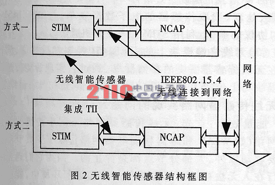
One of the solutions is wireless STIM (Intelligent Sensor Interface Model): STIM and NCAP are no longer TII interfaces (sensor independent interfaces), but transmit information via IEEE802.15.4 wireless (transceiver module). The information of sensors or actuators is transmitted by STIM to the NCAP terminal through the wireless network, and then connected to the wired network. In addition, the interface between NCAP and the network can be replaced with a wireless interface.
The second solution is a wireless NCAP terminal: STIM and NCAP are connected through a TII interface. The transceiver module of the wireless network is placed on the NCAP, and the other wireless transceiver module is connected to the wireless network to communicate with the wired network. In this solution, NCAP acts as a sensor network terminal. as shown in picture 2.
Because of power consumption, the wireless communication module is not directly included in the STIM, but NCAP and STIM are integrated in a chip or module. In this case, the TII interface between NCAP and STIM can be greatly simplified.
2 Realization of wireless smart sensor network
2.1 Wireless Smart Sensor
The realization mechanism of this design is that IEEE802.15.4 transmission module replaces the traditional serial communication module, and sends the collected data wirelessly [7].
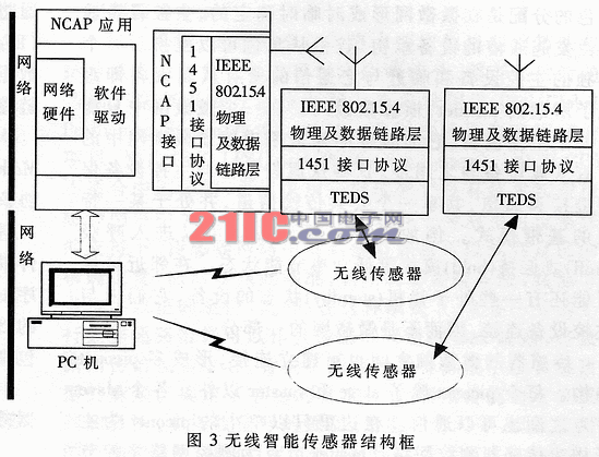
This article uses the IEEE802.15.4 physical protocol to construct a wireless intelligent network sensor system without NCAP, but it is not without NCAP, but here the PC is used to complete the NCAP function, that is, the NCAP here is virtual and is composed of PC; The on-site sensor is combined with a single-chip microcomputer (such as 8051) or DSP (digital signal processor) to form a STIM module, and then uses the 802.15.4 interface as the TII interface to connect with the virtual NCAP. The overall structure of the system is shown in Figure 3.
The sensor node module is mainly composed of the STIM module of the field. The STIM is mainly composed of the electronic data form (TEDS), sensor interface, field sensor, function module, TII interface and STIM core control module. Here, a microprocessor (such as single chip 89C51) is used as the core controller of the STIM module, IEEE802.15.4 is used to form the network interface or TII interface, program memory ROM is used to store the functional program module, and programmable EEPROM is used as the electronic data form storage unit. The I / O port connecting the single chip microcomputer and the field sensor is used as the sensor / actuator interface. 
The system uses a PC as a virtual NCAP module, the network environment is a bus network environment, the digital interface TII is an IEEE802.15.4 bus interface, and the STIM module is directly connected to the NCAP in a wireless manner. When data is sent, the field sensor will process the collected data through the signal conditioning circuit and signal processing circuit, and then send it to the wired network through the wireless interface; when receiving data, when the NCAP controller detects the data on the bus and receives it, select Through the corresponding STIM channel, it is sent to the node of the field sensor to realize the modification of the data collection parameters of the field node and the control of the action. The bottom layer (physical layer and data link layer) of STIM and NCAP is composed of 802.15.4 physical layer and data link layer. The 1451 interface protocol is responsible for data processing and conversion between the application layer and the bottom layer.
2.2 Wireless smart sensor network structure
The wireless sensor network is mainly composed of a PC host and a wireless sensor terminal module that complete the NCAP function. The architecture is shown in Figure 3. Each sensor terminal can visit each other, and can exchange data with devices on the wired network through the access point, and can even exchange information with remote devices through another access point on the wired network again. In this case, wireless has become a rich extension and supplement, generally used in places where the sensor needs to be moved frequently, or where the cables are dense and it is not appropriate to reroute.
If two sensors establish a wireless link, one of the devices will play a master role and the other will play a slave role. The assignment of roles is temporarily determined when the piconet is formed. The master control device is usually assumed by the device that initiated the communication, and the roles of master and slave can be interchanged. A single master device and all the slave devices that are in close communication with it form what is called a piconet, commonly known as a piconet. All slave settings in a piconet are synchronized with it. These slave devices maintain link and communication with the master device, share a common transmission channel, and are in a specific baseband mode. For example, the active slave device can enter a low-power energy-saving state such as sniff or hold mode. . There may be some devices in the standby state in the neighboring area. They are not connected to the main control device and are not part of the piconet.
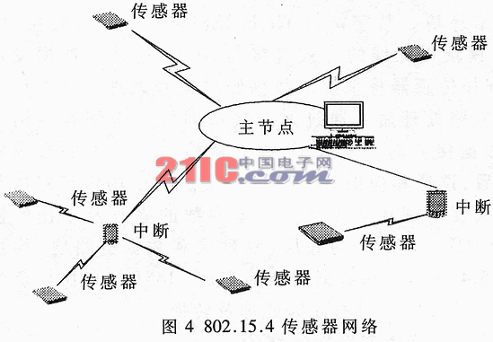
The piconet of the sensor can also establish a connection to form a multi-piconet structure. In addition to slave and master, each piconet can also communicate between slave nodes. Here only a single piconet is used as the backbone to build a sensor measurement and control network. The master node is the main control node of the measurement and control network, which realizes the function of information collection and processing, and the slave node is the sensor node. Considering that each sensor node is independent of each other, information fusion is only completed at the master node, so only the master point-to-slave point communication is realized, forming a star topology. The entire wireless sensor network function is divided into three layers: the lowest layer is various sensitive units, responsible for collecting the original information; the middle is the slave node based on the sensor intelligent module, responsible for the preprocessing of the original data (including filtering, compensation, digitization, etc.) and Send the data after processing; the uppermost layer is based on the master node of a common PC or other types of host computers (such as embedded computers), where all sensor information is processed at a higher level, such as spectral analysis, pattern recognition, and information fusion , Judgment and decision-making, etc. In the piconet, wired or wireless interrupts can also be used to expand the coverage of the signal and improve the network topology, as shown in Figure 4.
2.4 Software structure analysis realized by wireless sensor network
The lowest layer of the wireless intelligent sensor network is composed of IEEE802.15.4 protocol modules, including the physical layer and the data link layer.
Above the IEEE802.15.4 module is the 1451 control interface protocol. Through the control interface protocol, the 802.15.4 module can be easily embedded in various digital devices as a wireless transceiver terminal. The 1451 control interface protocol can complete the initialization of local devices, find terminal devices, establish links, exchange data, and increase or decrease the number of wireless terminal devices in the network. The interface protocol can be USB, RS232 or I2C interface. The host operates the IEEE802.15.4 module through the control interface and confirms the success or failure of the command through an event. The data exchange between the host and other devices in the network is also performed through the IEEE1451 control interface (its data link can be asynchronous or synchronous).
Smart sensor interface module STIM (Smart Transducer Interface Module) is located above the IEEE1451 interface protocol layer, and can use the data packets of this interface protocol layer to send STIM commands, events and sensor data.
The PC host software function that completes the NCAP function on the STIM host is defined as the application layer of the network system, mainly some application programs. The application layer is transparent to the protocol layers below it, but just sends STIM-defined packets to the lower-level STIM layer. The 1451 interface protocol layer packets are sent by physical communication ports such as RS232, RS485 or USB.
The application layer (PC host software that completes the NCAP function) and the wireless sensor terminal module (smart sensor interface module STIM) both communicate with the lowest layer IEEE802.15.4 module through the IEEE1451 interface protocol.
Based on the above analysis, the entire software system is divided into three parts:
(1) Applications running on NCAP-capable PCs: including user-oriented graphical user interface, STIM-oriented operation (mainly control and communication of smart sensor modules), and 1451 control interface on 802.15.4 module NCAP interface protocol for firmware communication. This part can be implemented in an object-oriented programming language, taking each sensor node as an instance object of a node class, and the application program accesses and controls each sensor node and each sensor on the node through the handle corresponding to the instance.
(2) The program embedded in the MCU of the smart sensor module (written in assembly or C language for different MCUs) mainly completes the collection, processing, reading of the electronic data form of the sensor, and communication with the IEEE1451 interface protocol 1. Use the STIM layer to communicate with the host computer.
(3) The IEEE1451 control interface protocol on the wireless terminal module is solidified in the memory of the wireless sensor module. Through it, the intelligent sensor module communicates with the application layer software on the host computer.
3 Problems and analysis of wireless sensor network implementation
Energy efficiency: First, wireless sensor networks are different from traditional wireless networks (such as WLAN and cellular mobile phone networks). Except for a few nodes that need to move, most nodes are stationary. Because they usually run in harsh and dangerous remote environments that are inaccessible to people, energy cannot be replaced, and designing effective strategies to extend the life cycle of the network has become the core issue of wireless sensor networks. These improvements involve the physical layer, data link layer, and network layer. The physical layer selects low-power modulation and hardware design. Second, adding an intermediate layer between the MAC layer and the network layer is responsible for making the sensor enter sleep mode or power saving mode as much as possible when not communicating, which can greatly reduce the energy consumption of the node. 
Routing and network control: In the early days of wireless sensor network research, people once thought that mature Internet technology plus Ad-hoc routing mechanism was sufficient for the design of sensor networks, but in-depth research showed that [2]: sensor networks have Traditional networks have significantly different technical requirements. The former is data-centric, and the latter is for the purpose of transmitting data. In order to adapt to a wide range of applications, the design of traditional networks follows the end-to-end edge theory [3], emphasizing that all processing related to functions is placed on the end system of the network, and the intermediate nodes are only responsible for the forwarding of data packets. For sensor networks, this may not be a reasonable choice. Some protocols and algorithms designed for self-organizing Ad-hoc networks may not be suitable for the characteristics and application requirements of sensor networks. The role of node identification (such as address, etc.) is not very important in sensor networks, because applications do not care much about the information on a single node; data processing, fusion, and caching related to specific applications on intermediate nodes are also necessary. In dense sensor networks, the distance between adjacent nodes is very short, and the low-power multi-hop communication mode saves power, while increasing the concealment of communication and avoiding long-distance wireless communication that is susceptible to external noise interference influences. These unique requirements and constraints have raised new technical issues for the research of wireless sensor networks.
Clock synchronization: The clock synchronization of wireless sensor networks is different from traditional sensor networks. The sensor is closely related to the actual physical environment. It must be synchronized with the physical clock, and it cannot use a relatively simple logical clock. The wireless sensor requires low energy consumption and time-synchronous data exchange is limited. The wireless sensor network has a large coverage area and is usually Ad The structure of -hoc does not use the traditional time synchronization method; the wireless media connection method is not reliable. For example, sensor networks and the actual physical environment. When the multi-sensor information of the monitoring system is fused, the host computer needs to know when each raw data is collected, and the sampling trigger requires that each node has a unified clock. Communication protocols and applications in sensor networks, such as TDMA-based MAC protocols and time-sensitive monitoring tasks. It also requires that the clocks between nodes must be synchronized. Designing a high-precision clock synchronization mechanism is a technical difficulty in the design and application of sensor networks. The 802.15.4 low-rate working group provides a coordination device protocol MDP (Mediation Device Protocol), which uses a pseudo-defined node to receive all communication requests in the network and coordinate the meeting time for both parties to the communication. This protocol does not require additional new hardware, and has little effect on the battery life of the node. However, the request for information has a great influence on the plan. The method of broadcasting time beacons is a simple and practical synchronization strategy. The basic idea is that the node records things with its own clock and then corrects it with the reference time broadcast by a third party. The accuracy depends on the measurement of this interval. This synchronization mechanism has sufficient accuracy in determining the sequence of monitoring events from different nodes. Consider simplifying the existing NTP (Network Time Protocol) protocol implementation complexity and planting it in the sensor network.
Positioning mechanism: The positioning mechanism and algorithm in wireless sensor networks include two parts: node positioning and external target positioning. The former is the basis of the latter. In terms of node positioning, GPS (Global Postitioning System) technology is commonly used. For some projects with low positioning accuracy requirements, LPS (Local Postitioning System) is applied. Since GSP is not suitable for China's national conditions, a mechanism that relies on its own technology to implement node positioning in sensor networks can be used. With the support of the Beidou No.1 double-star positioning system, some nodes in the sensor network can find their precise location, and then use this local reference algorithm to refer to this benchmark, and other nodes can also be correctly positioned. In addition, in this mode, the upstream data path of Beidou No. 1 can just be used as a sink link of the sensor network to transmit data back to the control center, eliminating the need to collect data by other means such as aircraft. The reference position of the node is determined, and the traditional positioning mechanism and algorithm, such as the strength, angle and time of the received signal, and the typical triangle algorithm, can be used to locate the external target. This is a relatively mature technology.
The wireless intelligent sensor network based on the 802.15.4 standard greatly improves the anti-interference of data transmission, and at the same time reduces various problems caused by field wiring, and the management of sensor nodes is also more convenient. It can be applied to large machinery and equipment monitoring occasions. Foreign products have been put into use. With the development of microelectronic technology and computer technology, the network function of microprocessing chips will be strengthened, and the combination of smart sensors and wireless communication networks will be easier. After the application of high-performance embedded processors, the functions of sensor networks will become stronger and stronger.
Dongguan V1 Environmental Technology Co., Ltd. , https://www.v1airpurifier.com