A constant voltage drive circuit with wide voltage input, high efficiency and high dimming ratio is proposed. In the hysteretic current control mode, the circuit has the advantages of simple structure, fast dynamic response, and no need for compensation circuit. Through external pins, LED switching, analog dimming and PWM dimming can be conveniently performed. The LED constant current drive circuit is based on CSMC's 1 μm 40 VCDMOS process, using HSPICE for simulation verification. The results show that the output current of the circuit can reach a maximum of 1.2 A in the 8-30 V input voltage range, and the output current accuracy can be controlled within 5.5% , Power efficiency can be as high as 97%.
0 Preface
With the development of LED technology, high-power LEDs have been widely used in the fields of light decoration and lighting, and at the same time, power LED driver chips are becoming more and more important. Since the brightness output of the LED is proportional to the current through the LED, in order to ensure the consistency of the brightness and chromaticity of each LED, it is necessary to design a constant current driver to make the LED current as uniform as possible.
Based on the light-emitting characteristics of LED, this paper designs a wide-voltage input, high-current, high dimming ratio LED constant current driver chip. The chip uses hysteretic current control mode and can be used to drive one or more LEDs in series. In the wide input voltage range of 6V ~ 30V, the average LED current is set by sampling the high-end current, the output current accuracy of the chip is controlled at 5.5%, and the chip can achieve analog dimming and PWM dimming through the DIM pin. After optimization The chip's response speed can make the chip achieve a high dimming ratio.
This article first analyzes the overall circuit, then introduces the design of each important submodule, and finally gives the overall simulation waveform, layout and conclusion of the chip.
1 Circuit system principle
Figure 1 is the overall chip architecture and typical application circuit diagram.
The circuit includes modules such as bandgap reference, voltage regulator, high-end current sampling, hysteresis comparator, power tube M1, PWM and analog dimming. In addition, the chip also has built-in under-voltage and over-temperature protection circuits, which can effectively ensure that the system can work stably under various adverse conditions.
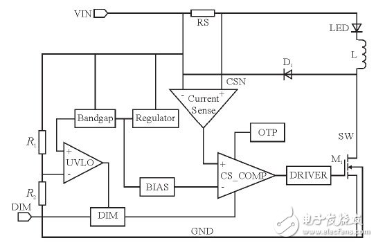
Figure 1 The overall equivalent architecture of the chip
It can be seen from Figure 1 that the inductor L, the current sampling resistor RS, and the freewheeling diode D1 form a self-oscillating continuous inductor current mode constant current LED controller. The chip adopts hysteresis current control mode, because the change of LED drive current is reflected in the change of the voltage difference across RS, so when the circuit is working normally, the current in the LED is sampled by the sampling resistor RS and converted into a certain proportion of sampling Voltage VCS, then VCS enters the hysteresis comparator, compares with the bias voltage generated by the BIAS module, generates a PWM control signal, and then passes through the gate drive circuit to control the power switch tube on and off.
The following specifically analyzes the working principle of the circuit. First, the chip will set two current thresholds IMAX and IMIN in the design. When the power supply VIN is powered on, the initial current of the inductor L and the current sampling resistor RS is zero, and the LED current is also zero. At this time, the output of the CS_COMP hysteresis comparator is high, the built-in power NMOS switch M1 is turned on, the potential at the SW terminal is low, and the current flowing through the LED starts to rise. Current flows from VIN to ground through inductor L, current sampling resistor RS, LED, and internal power switch. At this time, the slope of current rise is determined by VIN, inductor (L), and LED voltage drop. When the LED current increases to the preset value IMAX, the output of the CS_COMP hysteresis comparator is low. At this time, the power switch M1 is turned off. Due to the continuity of the inductor current, the current flows through the inductor (L) with another decreasing slope. , Current sampling resistor (RS), LED and freewheeling Schottky diode (D1), when the current drops to another predetermined value IMIN, the power switch is turned on again, the power supply charges the inductor L, and the LED current begins to increase again. When the current increases to IMAX, the control circuit turns off the power tube and repeats the action of the previous cycle, thus completing the hysteresis control of the LED current, so that the average LED current is constant.
From the above analysis, the average driving current of the LED is determined by the built-in thresholds IMAX and IMIN, so there is no feedback loop similar to the peak current control mode. Compared with the peak current control mode, the hysteresis current control mode is self-stabilizing and does not require a compensation circuit. In addition, the peak current detection mode dynamic response adjustment generally requires several cycles, while the hysteresis current control can be up to one cycle. The dynamic response of the system is stabilized, so the dynamic response of the hysteresis current control is more rapid. Of course, the hysteresis current control mode has the disadvantages of large output ripple and frequency conversion control, which is prone to frequency conversion noise. However, in high-power LED lighting driving applications, certain ripple changes and switching frequency changes will not affect the overall LED performance Have a greater impact.
Introduction
SCOTECH manufactures a full range of amorphous metal transformers, the core is made of amorphous metal with thickness 0.025mm which result in lower eddy current losses than CRGO core transformer, the core loss is around 70-80% of the regular CRGO core transformer, they are low loss energy saving transformers and environment friendly.
Scope of supply
Primary voltage up to 35KV
Rated power: up to 5MVA
Standards
SCOTECH`s amorphous metal transformers are designed and manufactured in accordance with all major international standards (IEC, ANSI, UL, etc.)
Why SCOTECH
Long history- Focus on transformer manufacturing since 1934.
Technical support – 134 engineers stand by for you 24/7.
Manufacturing-advanced production and testing equipment, strict QA system.
Perfect service-The complete customer service package (from quotation to energization).
Amorphous Transformer,Amorphous Core Transformer,Amorphous Alloy Transformer,Amorphous Metal Transformer
Jiangshan Scotech Electrical Co.,Ltd , https://www.scotech.com