Abstract: In the design of automotive electronic control equipment, electronic devices are the key devices in the equipment. The quality of the electronic device heat dissipation design directly affects the reliability of the entire system. The article introduces the design of a 50w radiator in a vehicle electronic control device, and introduces the thermal conductivity analysis and radiator design of the radiator from the perspective of use. The experimental data and simulation analysis results are compared and analyzed to verify the design. Effectiveness.
0 Preface
In recent years, electronic technology has been widely used and rapidly developed in automobiles, especially new energy vehicles. At the same time, people's increasing demands for automotive functions have made the integration of automotive electrical equipment higher and higher, and the integration of automotive electrical equipment functions. High Power. Miniaturization is the future development direction of automotive electronics.
With the thinning and miniaturization of electronic products. High performance. With the development of highly integrated IC devices, the heat generated by electronic equipment causes the internal temperature to rise rapidly. If this heat is not dissipated in time, the equipment will continue to heat up, the device will fail due to overheating, and the reliability of electronic equipment will The drop may even cause the chip to be broken down instantly and damaged. Therefore, the requirements for the heat dissipation of electronic products have been changed, and at the same time, the heat dissipation design technology of electronic products has been continuously improved.
1 Heat generation and heat conduction analysis of radiator
As a key component of the automotive electronic control equipment system, electronic devices must not only make the performance of the automotive electronic control equipment meet the requirements of the entire vehicle, but also ensure that the automotive electronic control equipment has sufficient safety and reliability. For automotive electronic control equipment provided under the prior art, in order to achieve higher energy density and power density, most power drive unit modules are composed of multiple power single tubes connected in series or parallel, so that the output voltage or output of the power module The current will be greatly increased to meet the driving requirements of the car. In the working process, the power-driven PCB assembly of automotive electrical equipment is the main source of heat generation.
Analysis of heat conduction process: the surface of the power device is mounted on the circuit layer, and the heat generated by the device is conducted to the metal base layer through the insulating layer, and then extended from the metal substrate to the outside of the module to realize heat exchange with the external environment and achieve heat dissipation for the device Figure l shows.
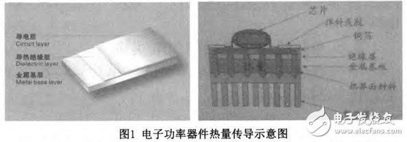
The metal used for the metal substrate depends mainly on the coefficient of thermal expansion. Thermal conductivity. strength. hardness. weight. Surface condition and cost. Aluminum substrates are basically used for metal substrates.
Aluminum radiators are made of aluminum alloy through extrusion molding. In order to increase the heat dissipation area per unit volume, corrugated teeth appear on the radiator after molding. This structure enhances the heat dissipation capacity of the radiator. Effectively reduces the internal thermal resistance between the power module and the heat sink, can quickly export the heat on the power module, and cool the power module in time; in order to supplement the defects in mechanical processing, a layer of 100 is coated on the plane of the heat sink The thermal paste of um fills the small space between the heat sink and the power module, which requires surface mechanical processing on the mounting surface of the power device during the processing process and ensures a certain flatness. Roughness. In short, the structural design of the radiator. The surface treatment and the coating of thermally conductive auxiliary materials create a good external heat dissipation environment for the power module, which can ensure the reliable and stable operation of the power module and extend the working life of the power module.
2 Radiator design
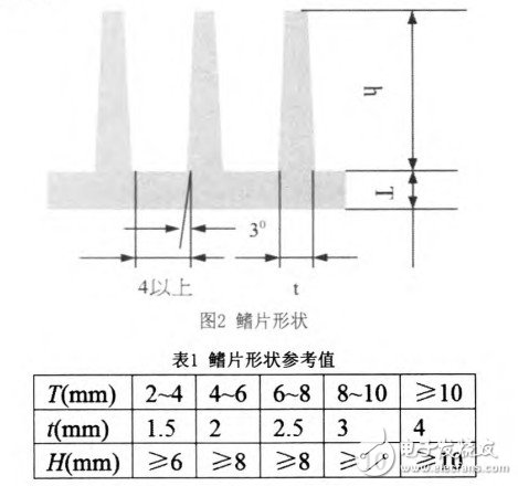
The fins dissipate heat by convection and radiation, with convection heat being dominant. With reference to the design information of the fin shape (as shown in Figure 2 and Table 1), the main dimensions are designed as follows:
(1) According to the installation position of the controller, the air resistance of the short air duct is small. Increase the heat dissipation surface area as much as possible, and choose fins parallel to the short side of the heat dissipation bottom plate.
(2) Space between fins. Since the air flow rate at the installation location of the BSG controller varies greatly with different operating conditions, and sometimes works under the operating conditions where the air flow rate is close to 0, in order to ensure that the heat dissipation bottom plate can effectively dissipate at a lower wind speed, sufficient fin Pitch. However, an excessively large fin pitch will reduce the number of fins and reduce the area of ​​the heat sink, thereby reducing the heat dissipation capacity of the heat sink. Natural convection will occur on the wall of the fins due to changes in surface temperature, resulting in laminar air flow on the wall. The thickness of the air layer is about 2mm, and the fin spacing should be above 4mm to ensure smooth natural convection. At this time, the tooth spacing of the heat dissipation bottom plate is about 8mm.
(3) Fin thickness. When the controller works in the starting state, the transient current of the power tube is large, so the controller has a large transient thermal shock, which requires that the heat sink bottom plate fins have sufficient thickness. When the shape of the fin is fixed, the balance between thickness and height becomes very important, especially when the fin is too thick and the height is not enough, it will cause difficulty in heat transfer at the front end, making the heat sink unable to increase efficiency even if the volume increases. When the heat sink is too thin and the height becomes shorter, the surface area is increased but the volume of the heat sink is reduced and the heat dissipation capacity is reduced. According to the reference value, the fin thickness is designed to be 4mm, and the draft angle is 3
(4) Since the power tubes are not evenly distributed on the heat dissipation bottom plate of the controller, in order to ensure effective heat dissipation, distribute heat dissipation fins as much as possible where the power tubes are concentrated.
(5) According to the basic formula of convection heat transfer, increasing the heat dissipation surface area of ​​the heat dissipation bottom plate as much as possible can effectively increase the heat dissipation capacity of the heat dissipation bottom plate, and can effectively increase the heat dissipation surface area of ​​the heat dissipation bottom plate by adding corrugated teeth on the fin surface. However, considering the influence of heat conduction and wind resistance, the depth of the corrugated teeth should not exceed 0.5mm.
Considering the above situation in combination with the overall shape of the PCB driver board and the controller, the design of the heat dissipation backplane is shown in Figure 3.

3 Thermal simulation and test analysis of radiator
3.1 Simulation results
Carry out CAE modeling and simulation on the designed radiator according to the following conditions:
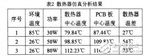
According to the total heat consumption power of 80W, the heat consumption power is evenly distributed on the radiator for simulation. Each simulation thermal monitoring point: 2 (PCB board. One at the center of the radiator), when the temperature of the center of the radiator changes at When the temperature does not exceed 1 ° C for 30 minutes, the heat sink is considered to have reached thermal equilibrium, and the simulation ends. The simulation results are shown in Table 2:
3.2 Test results

Experiments have measured that at 80W, 55W, and 30W, the temperature rise of the central equilibrium temperature of the heat sink is about 73 ° C. 54 ° C. 27 ° C, and the temperature rise of the center temperature of the PCB board is about 72 ° C. 55 ° C. 37 ℃ as shown in Figure 4.
4 Conclusion
By comparing the temperature rise data of simulation and test experiments, their temperature rises are not much different, and the temperature rise does not exceed 90 ° C in the absence of wind. At the same time, consider the installation location of the controller. Ambient temperature. Operating conditions and other factors, it can be seen that the center temperature of the radiator reaches about 110 ℃ is a normal situation, and the temperature of the power tube shell is at least 120 ℃ at this time, 160 ℃ away from its working limit temperature (at this time the drain current will be significantly reduced (Small) There is a certain appropriate distance, so the design of the radiator is more reasonable.
3.5 Bar Espresso Coffee Maker,Coffee Brewing Machine,3.5 Bar Espresso Machine,Gourmet coffee maker,Cafe espresso machine
FOSHAN FORTUNE ELECTRICAL APPLIANCE CO.,LTD , https://www.coffelady.com