With the development of modern communication technology, communication test instruments continue to evolve. Various new types of equipment have higher and higher requirements for the real-time response capability of the system. The real-time response performance of a communication test instrument becomes one of the key factors for the success of the system design. In many communication test instrument projects, the author successfully applied ARM processor, C51 microcontroller and other embedded systems as the main control chip, realizing the real-time control function of the instrument related modules. Therefore, a design scheme for real-time control using C51 microcontroller in a communication test instrument is proposed.
1 hardware design and implementation1.1 Overall design
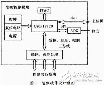
In the communication test instrument, the real-time control module mainly realizes real-time control effects on the radio frequency receiving frequency synthesizing, the radio frequency generating frequency synthesizing, the filter component, the radio frequency input module, and the radio frequency output module. A/D conversion of the RF detection signal to obtain data. Functions such as communication with the host computer.
According to the system function requirements to be realized, considering the system resources and the cost performance of the chip, the embedded system scheme based on C51 MCU is determined. The chip is Silicon Labs C8051F120 with 128 kB on-chip flash memory and 8&TImes. 1 024 + 256 Byte of on-chip RAM, can address 64 kB address space of external data memory interface, SPI, UART, timer, clock oscillator, PLL, etc., on-chip peripheral resources are rich, easy to control.
System resource allocation: RF receiving and transmitting frequency synthesizing module, including DDS, PLL, etc. The external control interface is a micro control interface, so the control is directly implemented by the address, data and control of the single-chip microcomputer. The working state of the filter component, RF input/output module, etc. is related to the level of the signal on the interface, so it is controlled by GPIO. The A/D conversion control uses the serial peripheral interface SPI. The communication with the host computer uses the RS-232 serial port. The overall design block diagram is shown in Figure 1.
1.2 Bus and I / O control design
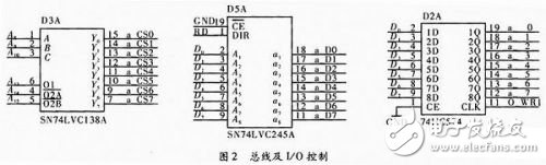
For the RF receiving frequency synthesizer and the RF transmitting frequency synthesizing module, the bus control is directly used. In order to avoid mutual interference when different modules are controlled, the bus address is decoded by the 3-8 decoder, and the chip selection signals of different modules are generated. At the same time, the data line passes through the bus transceiver to improve the load capacity. For the module with I/O control such as filter component, RF input/output, etc., the GPIO pin of 51 chip is not directly used, then the data bus is latched and the analog GPIO signal is used by the relevant module, as shown in Figure 2. , IO_ / WR1 is generated by B_ / CS7 and the microcontroller write line logic or later.
1.3 SPI and RS232 control interface
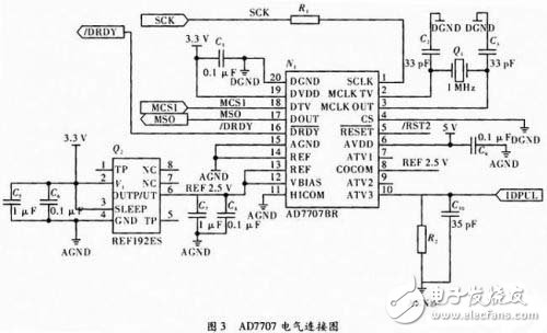
The C8051F120 chip itself has an A/D converter, but only 12 bits, which is not suitable for the system. Therefore, an AD7707 from Analog Devices is added to the chip. Its resolution is 16 bits, which is the ∑-△ architecture. , converted to the average of the input levels. Three channels, input level range up to ±10 mV~±10 V. According to actual requirements, the system uses AIN3 high level input port, Unbuffered mode, HICOM, REF- is connected to analog ground, VBIAS and REF+ are both connected to +2.5 V The reference voltage, analog power supply 5 V, digital power supply 3.3 V, can detect unipolar levels with an input range of 0 to 10 V. Its control interface is a synchronous serial port, which is directly controlled by the SPI of 51 chips. Figure 3 is an electrical connection diagram of the AD7707.
The communication between the MCU and the host computer uses the universal asynchronous transceiver UART, which is connected to the MAX3224 to convert the UART signal into an RS-232 signal for transmission. The MAX3224 operates at a low voltage of 3~5.5 V, but can generate RS-232 ±12 V voltage. Asynchronous serial communication can be achieved by simply connecting Tx, Rx, and ground. There are still some clocks, reset circuits, and power supplies in the system, which will not be described here.
2 software design and implementation2.1 main program framework
The main program flow chart is shown in Figure 4.
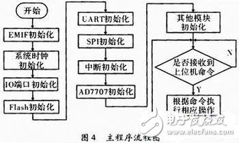
The main program is a sequential structure and is relatively simple. Mainly divided into two parts: First, the initial settings of each part of the system, so that it can work in a normal state. The second is the normal working cycle state. When the control command of the upper computer is received, the corresponding operation is performed, and when there is no command, it waits. For embedded programs, an infinite loop is necessary.
2.2 Serial communication program
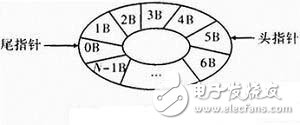
The serial communication program realizes the communication function with the host computer. In the specific operation, a circular queue is used to store the received upper computer commands, and the head and tail pointers are respectively used to point to the head and the tail of the team, and the command bytes are taken out to perform corresponding operations. The command is executed (the queue is empty), the flag is cleared, and a new command is awaited. As shown in Figure 5.
2.3 SPI communication program
The C51 uses the SPI master mode to communicate with the AD7707. The main mode write AD7707 is relatively simple. The MCU first writes 1 Byte of configuration data to the AD7707, which will automatically put the data into its own communication register. Then the AD7707 determines the register and data size to be written next according to the configuration value. The data that is subsequently input by the microcontroller is placed in the specified location. Before sending data to the C8051F120, first determine whether it can send data according to the value of the TXBMT bit in the SPICN register, and then write data to its SPIDAT register. The hardware will automatically send the data.
It is more difficult to read the AD7707 in the main mode. When C51 has set the communication register of AD7707, it indicates that the next operation is to read a register value of AD7707, C51 writes an arbitrary value to SPIDAT, then the data is serially shifted out on the SPI data line (MOSI), and the string is generated on the clock line. The line clock receives the clock from the device (AD7707), sends the prepared data to the MISO line and hands it to C51, and does not accept any value sent by the master device. C51 puts the transmitted serial data in the shift register. When the last bit is received, it is moved into the buffer. After reading SPIDAT, the data can be read.
2.4 Other software modules
Other software modules implement related functions by sequentially transmitting required data to the assigned corresponding address space according to the specific requirements of each part of the hardware.
3 ConclusionIn this paper, the embedded system with C51 MCU C8051F120 as the core control chip is proposed, which has been successfully applied to a communication test instrument. The system realizes the real-time control function of the whole machine through interrupt and query.
The mining intrinsically safe explosion proof VFD is used for frequency conversion of belt conveyor, scraper conveyor, fan, water pump, pump station and other equipment. This explosion proof motor starter has a variety of control modes to choose from, wide speed range, flexible speed control, strong anti-interference ability and long service life, which is the best choice for downhole frequency conversion speed control device.
Abb Vfd,Ac Variable Frequency Drive,Vfd Motor Drive,Flameproof Vfd,Explosion Proof Vfd,Explosion Proof Manual Motor Starter
FGI SCIENCE AND TECHNOLOGY CO., LTD , https://www.fgi-tech.com