Electronic enthusiasts: Tao Xianfang, a well-known domestic power technology expert, has worked tirelessly to solve problems for power engineers or enthusiasts during the double festival, and writes some technical problems and common power problems and solutions that engineers are very concerned about. The editor of the electronic enthusiast network is now compiled into several parts for the readers, "With the power expert Tao Xianfang learning power technology" series, including:

1. Influence of leakage inductance and distributed capacitance on output waveform (1)
2, the effect of leakage inductance and distributed capacitance on the output waveform (below)
3. Mathematical analysis of the effects of leakage inductance and distributed capacitance
4. Overvoltage protection circuit of power switch tube
5, the calculation of the power switch tube protection circuit parameters (on)
6, the calculation of the power switch tube protection circuit parameters (below)
7. Calculation example of RCD spike pulse absorption circuit parameters: Calculation of leakage inductance Ls of primary winding of switching transformer
8. RCD spike pulse absorption circuit parameter calculation example: calculation of peak pulse absorption capacitor capacity
9, RCD spike pulse absorption circuit parameter calculation example: the calculation of the peak pulse absorption resistance value.
The content is wonderful, please stay tuned to the electronic enthusiast network.
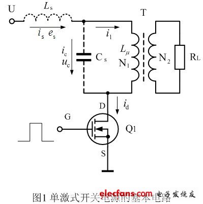
Figure 1 is a basic schematic diagram of a single-excited switching power supply. In the figure, T is the switching transformer, N1 and N2 are the primary and secondary coils of the switching transformer respectively; LS is the leakage inductance of the switching transformer, which is the excitation inductance of the primary winding of the switching transformer; CS is the distributed capacitance of the primary winding of the switching transformer, RL is The output load of the secondary winding of the switching transformer, Q1 is the power switch tube.
The distributed capacitance Cs of the primary or secondary winding of the transformer can be calculated as follows:
 (1)
(1)
In the formula,  The static capacitance between the ith layer and the i+1 layer coil, i = 1, 2, 3, • • •, n, n is the number of layers of the transformer primary or secondary coil of the total distributed capacitance sought; The average perimeter between the ith layer and the i+1 layer coil; Kui is the dynamic coefficient of the distributed capacitance between the ith layer and the i +1 layer coil,
 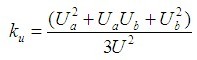 , which is related to the voltage applied across the capacitor, Ku is a coefficient less than one;
Ui is the standard potential difference between the i-th layer and the i+1-layer coil, and its value is generally equal to the sum of the operating voltages of the adjacent two layers of coils, that is, Ui=2U/n: , U is the primary or secondary coil of the transformer. The working voltage of the terminal; Uai and Ubi are the potential difference between x = 0 and x = h between the ith layer and the i +1 layer coil respectively; when the coil layer is pressed by S, Uai = 0, Ubi = Ui When the coil winding is in the Z winding method, Uai = Ubi = 1/2Ui.
If the influence of the secondary winding of the transformer on the primary coil is not considered, for a switching transformer with a power of about 100 watts, the distributed capacitance of the primary coil is between 100 and 2000 picofarads; if the respective capacitances of the secondary coil are also considered Into, the total distributed capacitance may be about doubled, because the conversion ratio of the distributed capacitance of the primary and secondary coils is squared. Therefore, the effect of distributed capacitance on the output waveform is large.
According to the working principle of the transformer, the switching transformer in Fig. 1 can also be equivalent to the circuit shown in Fig. 2.

In Figure 2, Ls is the leakage inductance, leakage inductance is also called leakage inductance, or distributed inductance; Cs is the distributed capacitance (total distributed capacitance), is the magnetizing inductance, and R is the equivalent load resistance. Let the inductance of the primary coil of the switching transformer be L, then L = Ls + Lu; and the distributed capacitance Cs, including the distributed capacitance of the secondary coil equivalent to the primary coil side, that is, the distributed capacitance of the secondary coil is also equivalent In the primary coil loop; similarly, the equivalent load resistance R, that is, the load RL of the secondary coil is equivalent to the resistance in the primary coil loop.
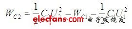
Let the distributed capacitance of the secondary coil be C2, and the distributed capacitance after the equivalent of the primary coil is C1, then the following relationship is obtained:
 (2)
(2)
In the above formula, Wc2 is the energy stored by the secondary coil distributed capacitor C2, Wc1 is the energy stored by C2 equivalent to the distributed capacitor C1 after the primary coil; U1 and U2 are the voltages of the primary and secondary coils, respectively, U2 = nU1, n = N2/N1 is the transformation ratio, and N1 and N2 are the number of turns of the primary and secondary coils, respectively. From this, we can find C1 as:
 (3)
(3)
The calculation methods of (2) and (3) can be used not only for the conversion of the primary and secondary coil distributed capacitance equivalent circuits, but also for the conversion of other capacitive equivalent circuits in the primary and secondary coil circuits, and Used to convert the load resistance. Therefore, C2 can also be any capacitor in the secondary coil circuit, and C1 is the equivalent of C2 to the capacitor in the primary coil circuit.
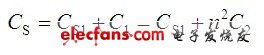
From this, it can be found that the total distributed capacitance Cs of the transformer in Figure 2 is:
 (4)
(4)
(4) where Cs is the total distributed capacitance of the transformer, Cs1 is the distributed capacitance of the primary coil of the transformer; and C1 is the capacitance of all the capacitors in the secondary coil circuit equivalent to the primary coil circuit; C2 is the secondary coil circuit All capacitors (including distributed capacitance and capacitance in the circuit); n = N2/N1 is the transformation ratio.
stainless material,never be rusty.easy to install,just press the Diffuser Strip Light into the bracket until it is fixed well.Before installation,put the bracket on any place you want,then use the attached screw to fix. In ordet to fix the led srtips,three brackets per meter is enough.And you can rotate the bracket to make the shape ,of course the basic position should be confirmed before fixing the brackets.paticular design,make the strips different from other products,the brackets are only attached strip light,not sold separately.
Mounting Brackets,Led Mounting Brackets,Metal Mounting Brackets,Wall Mount Bracket
Guangdong Kamtat Lighting Technology Joint Stock Co., Ltd. , http://www.ip68ledstrip.com