When studying various resonant circuits, it often involves the Q value of the quality factor of the circuit. Then what is the Q value? We will discuss in detail below.
1 is a series resonant circuit composed of a capacitor C, an inductor L, and a line resistance R of the leakage resistance of the capacitor and the inductor. The complex impedance Z of this circuit is the sum of the complex impedances of the three components.
Z=R+jωL+(-j/ωC)=R+j(ωL-1/ωC) (1)
The upper resistance R is the real part of the complex number, and the difference between the inductive reactance and the capacitive reactance is the imaginary part of the complex number. The imaginary part is called the reactance represented by X, and ω is the angular frequency of the applied signal.
When X=0, the circuit is in a resonant state, at which time the inductive reactance and capacitive reactance cancel each other out, that is, the imaginary part in equation (1) is zero, and thus the impedance in the circuit is the smallest. Therefore, the current is the largest, and the circuit is a purely resistive load circuit. The voltage and current in the circuit are in phase. When the circuit is resonant, the capacitive reactance is equal to the inductive reactance, so the effective values ​​of the voltages at both ends of the capacitor and the inductor must be equal.
The effective value of the voltage on the capacitor UC = I * 1 / ω C = U / ω CR = QU quality factor Q = 1 / ω CR, where I is the total current of the circuit.
The effective value of the voltage on the inductor UL=ωLI=ωL*U/R=QU Quality factor Q=ωL/R
Because: UC=UL, so Q=1/ωCR=ωL/R
The ratio of the voltage across the capacitor to the applied signal voltage U UC/U = (I*1/ωC)/RI=1/ωCR=Q
The ratio of the sensed voltage to the applied signal voltage U UL/U = ωLI / RI = ωL / R = Q
From the above analysis, the higher the quality factor of the circuit, the higher the voltage on the inductor or capacitor than the applied voltage.
Circuit selectivity: The total current of the circuit of Figure 1 is I=U/Z=U/[R2+(ωL-1/ωC)2]1/2=U/[R2+(ωLω0/ω0-ω0/ωCω0)2]1 /2 ω0 is the angular frequency at which the circuit resonates. When the circuit resonates: ω0L=1/ω0C
So I=U/{R2+[ω0L(ω/ω0-ω0/ω)]2}1/2= U/{R2+[R2(ω0L/R)2](ω/ω0-ω0/ω)2}1 /2= U/R[1+Q2(ω/ω0-ω0/ω)2]1/2
Because the total current of the circuit when the circuit resonates is I0=U/R,
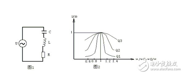
Therefore, I=I0/[1+Q2(ω/ω0-ω0/ω)2]1/2 has: I/I0=1/[1+Q2(ω/ω0-ω0/ω)2]1/2 The function curve of this formula. Let (ω/ω0-ω0/ω)2=Y
The curve is shown in Figure 2. There are three curves, corresponding to three different Q values, among them Q1 "Q2" Q3. It can be seen from the figure that I/I0 is less than 1 when the applied signal frequency ω deviates from the resonant frequency ω0 of the circuit. The higher the Q value, the faster the current drops at a certain frequency offset, and the sharper the resonance curve. That is to say, the selectivity of the circuit is determined by the quality factor Q of the circuit, and the higher the Q value, the better the selectivity.
Reset Lockout
Prevents reset if GFCI is damaged or failed to provide ground fault protection
Complies with NEC ® requirement, by blocking access to the contacts unless the plug is fully inserted
Only 1.22" Protrusion into Wallbox
Takes up to 20% less space in the wallbox vs. other GFCIs for easier installation
Multi-functional Status Indicator Light
Red and Green LED indications provide simple, intuitive feedback on power, voltage and protection status
Terminals Withstand
Tolerate high-torque;power tool installation;and prevents wire pullout
Tamper-Resistant Shutter mechanism
TR GFCI UL,New Version TR GFCI UL,TR Socket GFCI Outlets,New VGersion GFCI with TR Receptacle
Hoojet Electric Appliance Co.,Ltd , https://www.hoojetgfci.com