Studying the modulation characteristics of light-emitting diode (LED) devices and the luminescence characteristics under high-speed modulation conditions is one of the key issues to improve the performance of new visible light communication systems. The improvement of modulation characteristics of LED devices can significantly expand the application range of visible light communication systems. Based on the FM characteristics of LED devices, by analyzing the structure of light-emitting devices and packages and other key optoelectronic properties, suggestions are made to improve the response rate of LED devices and improve the modulation bandwidth of LEDs by reducing RC time and carrier spontaneous emission lifetime.

1 LED device modulation bandwidth and its test
Bandwidth generally refers to the bandwidth occupied by the signal. When describing a channel, bandwidth refers to the maximum bandwidth that can effectively pass the channel signal. The modulation bandwidth of a light-emitting diode (LED) is the bandwidth of the device that can carry the maximum signal when the modulation signal is loaded. Generally, the AC power output of the LED is reduced to half of a low-frequency reference frequency (eg, -3 dB). The frequency is determined by the modulation bandwidth of the LED. The modulation bandwidth of LED is the decisive factor of channel capacity and transmission rate of visible light communication system, which is affected by many factors such as the actual modulation depth and volt-ampere characteristics of the device.
The test of the modulation bandwidth of the LED device is usually to load an analog signal (such as a sinusoidal signal) on the device under DC operation, and measure the curve of the optical power signal as a function of frequency to determine the bandwidth.
Figure 1 shows a device modulation characteristic test system [1-3]. It mainly includes the signal transmitting end and the receiving end. At the transmitting end, the signal from the signal generator is amplified by the power amplifier to increase its modulation depth; then, the signal is applied to the DC bias of the driving LED so that the LED emits a modulated optical signal; at the receiving end, the photodetector emits light The signal is converted into an electrical signal, filtered and amplified, and output to the oscilloscope.
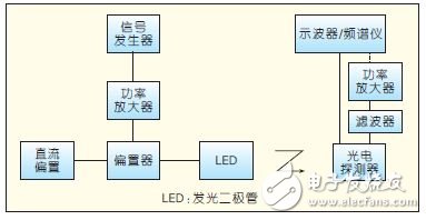
Figure 1 device modulation characteristics test system composition
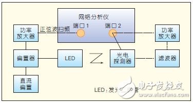
Figure 2 device modulation characteristics test system components
Figure 2 is another device modulation characteristic test system [4-5]. At the heart of the system is a network analyzer that integrates the functions of signal generation, detection, and processing to enable higher frequency testing. Measuring the LED modulation bandwidth, mainly focusing on the S21 parameter of the network analyzer, that is, the input power of port 2 of the network analyzer/the output power of port 1.
2 Influencing factors and improvement methods
In general, the factors affecting the modulation characteristics of LEDs mainly depend on the following two aspects [6]: RC time and carrier spontaneous emission lifetime. The active area of ​​the LED is a multi-quantum well structure with charge-limiting effect. The rise and fall time in the response process is called RC time, which is mainly affected by the junction capacitance and has a delay effect on the signal. The carrier in the active region of the device The spontaneous radiation lifetime directly affects the time it takes for carriers to escape from recombination to photons.
2.1 Reduce RC time
Figure 3 shows the small signal equivalent circuit of the LED [7]. This small signal equivalent circuit is actually similar to the equivalent circuit of a laser at a threshold voltage. Since the laser device operates in a spontaneous emission state at a threshold voltage and the stimulated emission process has not yet started, the LED also uses the equivalent circuit [8-11].
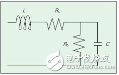
Figure 3 LED small signal equivalent circuit
Where C is the junction capacitance, RD is the junction resistance, RS is the equivalent series resistance, and L is the parasitic inductance caused by the lead. The researchers can obtain these corresponding key parameters through experimental measurements and theoretical fitting [7-8]. The capacitance and geometric capacitance obtained here are an order of magnitude, and the resistance is similar to the geometric resistance. Therefore, the size of the device can effectively adjust the equivalent circuit parameters and thus increase the device bandwidth.
It is a relatively straightforward way to reduce the RC time by the size of the device to improve the LED modulation bandwidth. The effect of size on LED bandwidth was studied by designing a set of LED devices of different sizes (junction area, p-GaN and junction contact area) [4]. A device with a larger active area has a smaller modulation bandwidth at the same current density. The reason is mainly because the equivalent junction capacitance is larger, and the effect of the increase in capacitance on the bandwidth is more significant than the effect of the resistance reduction. This result is consistent with the results of J.-W. Shi et al. [6] of Taiwan's successful university. Figure 4 shows the frequency response curves of experimental devices A and B at different drive currents. A device p-GaN has a larger contact area with the junction.
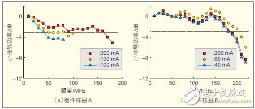
Figure 4 Frequency response curves of two different sized devices at multiple drive currents
Figure 4 also reflects the effect of different currents on the LED bandwidth. At high currents, the carrier concentration increases, resulting in a composite enhancement in the multiple quantum wells and a reduced carrier lifetime of the carriers.
Chien-Lan Liao et al. [12] of Tsinghua University in Taiwan used a gallium-doped (Ga) zinc oxide (ZnO) film GZO to effectively reduce the junction capacitance. Figure 5 shows a schematic diagram of a blue LED structure with a current limiting layer. Since the p-type GaN layer is carved out of the mesa and the electrode is formed on the p-type, the effective capacitance can be reduced. Moreover, the electrode adopts a ring structure, and the GZO film with large lateral resistance is used to realize current limiting, so that the current is mainly transmitted in the vertical direction, that is, GZO realizes the opposite function to indium tin oxide (ITO), and suppresses current expansion. Therefore, the actual junction capacitance will become smaller, thereby achieving an increase in the LED modulation bandwidth. With this ring electrode design, the device has a 3 dB bandwidth of 225 MHz.
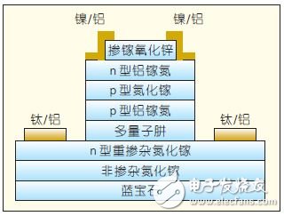
Figure 5 Epitaxial wafer structure using GZO as current limiting layer
Xu Jinyu and others from Taiwan's Central University [13] also effectively increased the LED modulation rate by means of series connection, and the starting point is also based on the optimization of RC time. If N identical LEDs are connected in series, the resistance value will increase linearly by R total = N · R, while the capacitance value decreases linearly by C total = C / N. This way, although the RC time has not changed. However, in general, the device needs to be externally connected, so the actual RC is (N·R+R0)·C/N, so it is smaller than the RC (RC+N·R0C) of a single LED of the same area, so that the modulation bandwidth can be effectively improved.
Dmx Led Bar 2722 is dmx512 rgb led lighting, width is 27mm and height is 22mm. DMX LED Bar 2735 is dmx512 rgb led lighting, width is 27mm and height is 35mm. We offer rgb led bar dmx lighting, similiar with american dj lighting or RC lighting, the LED Pixel Bar is Color Changing Light Bar. Led Rgb Bar , led rgbw bar is available. pixel bar have 1 led light bar, 2 led light bar, 3 led light bar, 6 Led Light Bar. It's dmx512 programming, the address have two type, one is auto address, another is manual address. That's to say we have led bar auto and led bar manual. Auto led bar, you don't need assign dmx address, it's convenience for event show and led light rental. Manual led bar, you need assign dmx address by Address Writer before light up, for DJ club, architecture light, it's ok. Maybe you want to know how to install a led light bar, don't worry, we have bracket, so that you can fix the bar easily. Regarding color changing led light bar, you can control by Led Controller.
Photo show of DMX LED Bar:

Dmx Led Pixel Bar,Dmx Led Bar,Dmx Light Bar,Led Rgb Bar
Shenzhen Iseeled Technology Co., Ltd. , https://www.iseeledlight.com