The earlier magnetic sensors were gradually developed along with the advancement of magnetic measuring instruments. In many magnetic measurement methods, most of the magnetic field information is converted into electrical signals for measurement. In a magnetic measuring instrument, a "probe" or "sampling device" is a magnetic sensor. With the rapid development of information industry, industrial automation, transportation, power electronics, office automation, household appliances, medical instruments, etc., and the popularity of electronic computer applications, a large number of sensors are needed to measure and control non-electrical parameters. , converted into a computer-compatible signal as their input signal, which provides an opportunity for the rapid development of magnetic sensors, forming a considerable magnetic sensor industry.
The proximity switch is one of many types in the sensor family. It is made of an advanced technology using electromagnetic working principle and is a position sensor. It can change the positional relationship between the sensor and the object, and convert the non-electricity or electromagnetic quantity into the desired electrical signal to achieve the purpose of control or measurement. The principles currently used by proximity sensors are inductive, magnetic, optical, ultrasonic, and capacitive. This article describes several commonly used proximity switches and explains their principles and applications.
1. Capacitive proximity switch

principle:
The capacitive proximity switch's sensitive components consist of a conductive plate system that can be viewed as one or a group of capacitors. The presence or passage of electrical conductors and dielectrics in the vicinity of the plate changes the electrostatic field distribution in the plate system, thereby changing the sensitive components. capacitance. The signal processing circuit detects this change and can detect the proximity of the target object. In contrast, capacitive sensors have a simpler structure, higher operating impedance, and lower power consumption. In addition, they can be protected from parasitic or intentional interference by frequency-locked or spectrally extended carrier modulation techniques. Other programs are difficult to meet the designer's requirements.
The stability and reliability of the mechanical switch is poor. The magnetic sensitive mode consumes too much power and is also susceptible to external magnetic fields. The optical and ultrasonic sensors are more complex and susceptible to external interference.
2. Inductive proximity switch

principle:
The Inductive Proximity Switch (GDKG) is a position sensor with a switching output that consists of an LC high frequency oscillator, a signal trigger and a switching amplifier. The coil of the oscillating circuit generates a high frequency alternating magnetic field that is released via the sensing surface of the sensor. When a metal object approaches the oscillation induction head capable of generating an electromagnetic field, an eddy current is generated inside the metal object, and the eddy current reacts to the proximity switch, so that the proximity switch oscillation capability is attenuated, and the parameters of the internal circuit change, when the signal trigger When this attenuation is detected, it is converted into a switching electrical signal. It is thus recognized whether the metal object is close to the switch, thereby controlling the on or off of the switch.
The object that this proximity switch can detect must be a metal object.
3. Hall type proximity switch

3.1 Principle
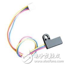
When a current-carrying metal or semiconductor wafer is placed vertically in a magnetic field, a potential difference is generated at both ends of the sheet. This phenomenon is called the Hall effect. The potential difference between the two ends is called the Hall potential U, and its expression is: U=K·I·B/d, where K is the Hall coefficient, I is the current passing through the sheet, and B is the applied magnetic field. The magnetic induction of Lorientz, d is the thickness of the sheet. It can be seen that the sensitivity of the Hall effect is proportional to the magnetic induction of the applied magnetic field. The Hall proximity switch belongs to this active magnetic/electrical conversion device. It is based on the Hall effect principle and is fabricated by an advanced integrated package and assembly process. It can easily convert the magnetic input signal into actual. The electrical signal in the application has the requirements of practical operation and reliability in industrial applications. The input of the Hall proximity switch is characterized by the magnetic induction B. When the B value reaches a certain level (such as B1), the trigger inside the switch is flipped, and the output level state of the Hall proximity switch is also reversed. The output terminal generally uses transistor output, similar to the inductive proximity switch: NPN, PNP, normally open, normally closed, latched (bipolar), dual signal output.
The Hall proximity switch is one of the magnetic proximity switches. It has the characteristics of no electric shock, low power consumption, long service life and high response frequency. The interior is made of epoxy resin and sealed into an integrated structure, so it can be used in various harsh environments. Work reliably. It can be applied to proximity switches, pressure switches, odometers, etc. It is a new type of electrical accessories. The Hall-type switch has higher response frequency than the inductive switch. It is triggered by magnetic steel, and the inductive type is triggered by magnetic conductive metal. The Hall-type switch sensing distance is related to the performance of the sensor itself, and also related to the magnetic field strength of the selected magnetic steel.
3.2 Hall proximity switch term explanation
1 Magnetic induction: The magnitude of the magnetic field strength that the magnetic steel requires when the Hall proximity switch is in operation. The general magnetic induction value B is 0.02~0.05 Tesla.
2 Response frequency: The number of times the Hall switch is allowed to cycle during the 1 second interval as specified.
3 Output status: divided into normally open, normally closed, latched and other types. For example, when there is no detected object, the load of the normally open Hall switch is not operated due to the cutoff of the output transistor inside the Hall proximity switch; when the object is detected, the transistor is turned on and the load is powered. jobs.
4 Output form: divided into NPN, PNP, normally open, normally closed, multi-function and other common forms of output.
5 Movement distance: The movement distance is the spatial distance from the reference position (the sensing surface of the Hall switch) to the reference position measured at the time of the switching operation to the detection surface when the object to be detected moves in a certain manner. The rated operating distance refers to the nominal value of the operating distance of the Hall switch.
6 Return distance: The absolute value between the action distance and the reset distance.
3.3 Application examples
Since the speed signal is in the form of a pulse, when the magnetic field strength of the measured magnetic object reaches 25 millitesla or more, the output is a standard TTL level. Using the intelligent control and calculation functions of the computer, the tachometer is simple and precise. For example, if the 3020 Hall-type proximity switch is used, the single-chip microcomputer uses 8031 ​​(its crystal is 6MHz and 0.5MHz after dividing by 12), then the measured maximum speed is 0.5MHz, and the minimum measurement speed can be infinitely low.
3.4 Precautions
1 DC type Hall proximity switch products use a DC voltage of 3~28V, and its typical application range generally uses 5~24V. Excessive voltage will cause the internal Hall component parameters to change with the voltage increase. Stability, and too low voltage is easy to let the external temperature change affect the magnetic field strength characteristics, causing circuit malfunction.
2 When using the Hall proximity switch to drive the inductive load, please connect the freewheeling diode to both ends of the load. Otherwise, the transient high voltage pulse during the long-term operation of the inductive load will affect the service life of the Hall switch.
3 General Hall proximity switches are manufactured using the SMD process and are shipped after rigorous testing. Under normal circumstances, there is no damage, but in order to prevent accidental events, the user should check whether the wiring is correct before turning on the power and verify whether the voltage is rated.
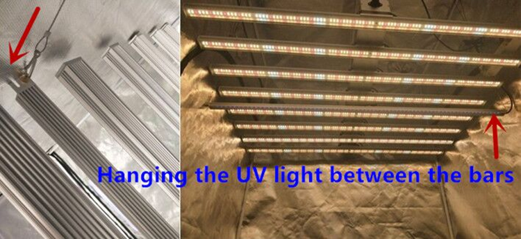
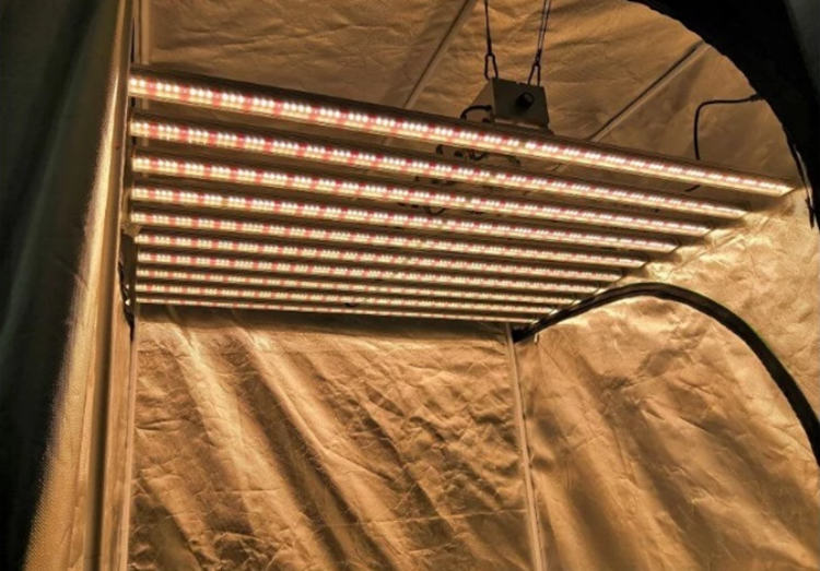
LED Grow Light Bar Full Spectrum 640W,the best Led Grow Light Bar use Samsung Quantum Board grow led, 640w with 8pcs grow bar , Quantum Board Samsung pane works well for all plant growth. 4/6/8/10/12 bars available too.
Application: lettuce, orchid, organic herbs, pepper, strawberries, succulent, hydroponic, medical plants.
Delivery:Sample 1-5days, bulk order negotiate.


Led Grow Light Bar Full Spectrum 640W
Grow Light Bar Full Spectrum ,Led Grow Bar Full Spectrum Hydroponic ,Led Grow Light Bar Full Spectrum,Led Grow Light Full Spec
Shenzhen Wenyi Lighting Technology Co., Ltd , https://www.wycngrow.com