Introduction Chip programming and self-loading are the basic conditions for a DSP system to run smoothly. In the DSP loading technology, there has been a lot of literature and work results, which better solve many basic problems of DSP self-loading. The traditional programming/loading scheme requires repeated external emulators, configuration jumpers, and only the projects running on the specified address space when debugging and updating programs. These have little effect on the system in the installation and commissioning phase, but in DSP systems such as aerospace equipment, large machinery or other harsh environments, where it is difficult to directly connect the emulator, it cannot be implemented by ordinary programming/loading schemes. Update and debug.
By analyzing the loading principle of DSP system, a remote multi-loading DSP system design based on TI's C6x chip is proposed. The system is composed of a communication chip, a DSP, an external dynamic memory, and an external flash memory (Flash), and has a remote programming and program selection loading function. The system program is also highly secure when it is updated. Even if the programming process is interrupted, the new project can continue to be burned and run after the next power-on.
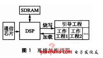
1 System structure In order to meet the functional design requirements, the loading and writing system needs to connect external dynamic memory (SDRAM), erasable memory (Flash), communication chip, etc. in addition to the DSP chip necessary for DSP system operation. The system structure is shown in Figure 1. Among them, the communication chip is responsible for data exchange with the remote control end, the SDRAM stores DSP work code and data, and the "boot project" responsible for guiding the actual work project and the "work work" code data responsible for the actual information processing task are respectively stored in Different flash spaces.
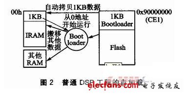
2 Implementation Scheme Firstly, the guiding principle of the ordinary secondary loading project of the C6x series DSP is briefly explained. When the DSP of the self-loading mode is powered on, the data of a certain length (1 KB of the C671x series) is copied from the start address of the CE1 space (0x90000000) to the internal memory 0 address, and the program is executed from the 0 address. Due to the limited length of the copied data, a self-loading project with a length greater than 1 KB usually needs to perform a secondary loading operation. Therefore, the project must include a Bootloader module with a length less than 1 KB. The module is subjected to a secondary loading data movement operation. Code composition. After the project is compiled, the Bootloader module is programmed in the first 1 KB address space of the Flash. After the system is powered on and reset, the DSP automatically transfers it to the 0 to 1 KB address space for execution (first load), and the module is used. Data movement of other data segments (second load). After the data transfer is over, the Bootloader module jumps the PC pointer to the _c_int00 address segment and finally enters the main function to start the entire project. The entire self-loading process is shown in Figure 2.
Obviously, only the data stored at the very front end of the DSP CE1 space can be automatically loaded and run. In order to make the system have communication, programming and multi-boot functions at the time of power-on, it is necessary to store the boot project with the above functions in the space where the CE1 base address starts.
The DSP multi-boot technology is developed on the basis of the loading technology of the ordinary DSP system. The project with the functions of booting, communication, programming, and memory check and error correction is independently stored in the DSP CE1 space as the boot project, and is automatically loaded by the DSP. Run; and store the application code with different functions in other memory, waiting for the boot project to load according to the function needs.
The boot project is automatically run by the DSP, and then communicates according to remote commands or according to the execution of the predetermined program flow, updates the work engineering code, or carries and runs the bootloader segments stored in other space work projects, thereby guiding the work of different functions. With this engineering separation operation technology, the code in the space electronic device memory can be updated, error-corrected and loaded by the remote end or automatically, and even multiple work projects can be switched to meet the functional requirements in different application contexts; Even if there is a failure during the update or switching process, the system can be returned to the normal working boot project for system maintenance or re-update after the system reset, with anti-burn function.
2.1 Guided Project Design The boot project is the program responsible for communicating with the remote control terminal, obtaining the work project code, and completing the programming and booting work project loading and running. The boot project needs to have functions such as self-loading, uploading verification data, and programming guidance.
2.1.1 Self-loading function The guiding project adopts the loading/programming mode of ordinary engineering, and needs to be programmed and solidified in the emulator mode after the production of the product is completed. Since the boot project has functions such as communication and programming, its data length generally exceeds the 1 KB DSP automatic transfer length limit. Therefore, the boot project in the system needs to be designed as a project with secondary loading capability and programmed. At the forefront of the DSP memory CE1 space, it is the boot project that ensures that the DSP first loads and runs during autoboot.
When designing the boot project self-loading function, it is different from the normal secondary loading project:
1 program storage address should be limited to avoid occupying work engineering space;
2 Bootloader of the boot project must be placed within the first 1 KB of the CE1 space, enabling the DSP to automatically load and run at power-on.
2.1.2 Communication Function The communication module is mainly composed of communication chip and communication control logic, and is responsible for completing communication between the remote control terminal and the DSP. Different communication chips and link protocols can be selected depending on the application. The following mainly considers the application layer protocol design.
(1) Data uploading and verification According to the method in the reference, in order to burn the work project online to the Flash memory space, it is first necessary to download the compiled project file and convert it to rewritable. Hex file. Through the communication module, the remote device can send and store the hex file in the DSP external memory. The wrong hex file data may cause the DSP to work abnormally when booting the work project, or even fail to load properly. Therefore, the remote end should verify the saved data after completing the data upload. The more intuitive method is to return the data received by the DSP through the communication interface, and the remote device will make this data original. The hex files are compared to determine if the data is correct.
(2) Programming command After the data verification is completed, the remote terminal sends a programming command to the DSP to start programming.
(3) Boot instructions If it is necessary to run the corresponding work project according to the function, the remote terminal issues different boot commands to the DSP to guide the work of the corresponding address. According to the automatic loading principle of DSP, the guiding project needs to follow the same steps.
The communication function of the boot project can be performed in an interrupt or query manner. If you do this in interrupt mode, you need to properly handle the interrupt vector table and enable the corresponding interrupt. When the boot project exits, the communication port and interrupt resources used must be shut down.
2.1.3 Online Programming Function In order to save data using a non-volatile memory chip, early DSP systems must use a dedicated programming device. With the advancement of storage technology and control technology, some DSP chips already have the ability to erase and write directly to the Flash chip.
Since the boot project and the work project share a flash storage medium, when erasing the storage space of the work project, sector erasure is required instead of the entire chip erase to ensure that the boot project is not overwritten. The protection of the boot project can also be achieved by writing protection to the sector in which it is located. The write protection operation ensures that regardless of the success of the programming of the work project, the boot project will remain in the Flash chip after the first successful burn, and can be communicated, programmed and booted each time the power is turned on. .
In some occasions where the reliability of the equipment is critical, the guiding project can also be stored separately in a piece of PROM. After a single burning and curing is completed, the space where the guiding project is located cannot be modified. This completely avoids the memory performance degradation caused by the repeated erasing of the flash chip, and the problem of erroneously erasing the booting project during programming.
The programming process is similar to the erasing process and can be designed with reference to the instructions in the references.
2.1.4 Load Boot Function After completing the programming of the work project file, you need to guide the work project to start working according to the remote console command. According to the principle of DSP self-loading, the boot project must first close all used DSP resources, and copy the Bootloader program of the work space in other spaces of the Flash memory to the space starting from the address of the DSP internal memory 0 (this process simulates Figure 2 shows the data movement when the DSP is automatically loaded. Then, the program pointer jumps to the bootloader start address of the work project and starts running. The remaining data segment of the entire work project is sequentially loaded into the dynamic memory of the DSP by the Bootloader program of the work project, and finally jumps to the start address of the work project, and the main program segment of the work project is started.
The advantage of booting by the boot project is that the DSP can only automatically load the data in the beginning of the CE1 space, and the user-designed boot project can load the data in any readable storage space; the DSP can only load the program at power-on time. The boot project can convert and load different application engineering programs at any time.
2.2 Work Engineering Design Work engineering is the project used to complete the real information processing requirements of DSP system. Its design is consistent with the basic principle of ordinary secondary loading DSP engineering, but it needs to be adjusted for several aspects of double secondary loading function:
1 memory setting. Since all external devices and RAM used by the boot project can be reused, it is only necessary to reserve the flash address space used by the boot project when configuring the memory space in the work project. All other boot project memory can be reset before normal operation.
2ISTP (Interrupt Service Table Pointer) setting. Each project has an independent interrupt vector table, so the interrupt vector service pointer needs to be reset when the project is switched to ensure that the new project responds correctly to the interrupt.
3 other resource settings. In order to simplify operations and save resources, DSP resources should be occupied as little as possible in the boot project. In addition to the above memory and interrupt resources, the boot function may use other resources such as timers, MCBSP, EDMA, and so on. Before booting the work project, all the devices need to be shut down; at the same time, after entering the work project, these peripheral resources need to be re-initialized to avoid device conflicts.
Conclusion By analyzing and using DSP loading and running mechanism, this paper designs a multi-loading DSP system with remote updating capability. The program interface is used to remotely update the program code, and the DSP project with different functions is programmed in the same Flash chip, and the program running with different functions can be selected through external communication instructions, so that the DSP system can be updated and operated flexibly and safely.
The remote multi-boot DSP solution completes the function design of remote online DSP code burning and guiding operation with less system resources without changing the overall framework of the system. At the same time, due to the practice of guiding engineering and separating work and engineering, Strongly robust. The system has excellent characteristics such as burning, disassembly, anti-burning and death, and can be widely used in aerospace, mechanical and control system design.
We offer rechargeable li ion and Lipo Battery cells from industry's leading manufacturers, Panasonic cells, Sanyo cells, Moli cell, ATL cells, BAK cells, DLG cells, HYB cells, Samsung cells, LG cells, Maxell Cells. With contacts inside big manufacturers, we are able to supply authentic cells in wide variations of sizes, capacities, and power performances to meet your needs. In addtion we provide processing service to add proteced PCB in cell, to put heat shrink tubes, wires with designated connector, or to design unique plastic case with coaxial DC port.

Rechargeable Batteries,Rechargeable Lithium Batteries,Rechargeable Cell,Lithium Ion Rechargeable Batteries
Asarke Industry Co., Limited , https://www.asarke-industry.com