With the development of the times, mobile phones have more and more functions, not only can take beautiful photos, play audio and video streaming files, but also access a variety of services - and now gradually become personal trainers. When equipped with sensors or connected to wearable sensors, these devices can be used to monitor people's daily activities and personal health. Driven by increasing health awareness, people are beginning to focus on measuring vital signs such as heart rate, body temperature, blood oxygen saturation, blood pressure, activity levels (calorie) and calorie burns—and tracking the daily trends of these parameters.
A universal sensor front end with multiple sensors can now monitor these parameters. The bigger challenge is to minimize size and extend battery life. This article will discuss solutions for the rapidly growing market for wearable electronics.
Most important vital signs
Pulse or heart rate is one of the most important parameters to monitor. In addition to the number of beats per minute, you should also check the relationship between cardiac behavior and activity. Heart rhythm is also very important because the rapidly changing heart rate is a sign of heart disease.
Monitoring of heart rate and cardiac activity is usually achieved by measuring electrophysiological signals using an electrocardiogram (ECG). Electrodes connected to the body measure the signal generated by the electrical activity of the heart tissue. The professional diagnostic system is based on this principle, which can connect up to 10 electrodes in the chest and limbs. The ECG provides detailed information about the different components of the heartbeat (P wave, QRS and T waves).
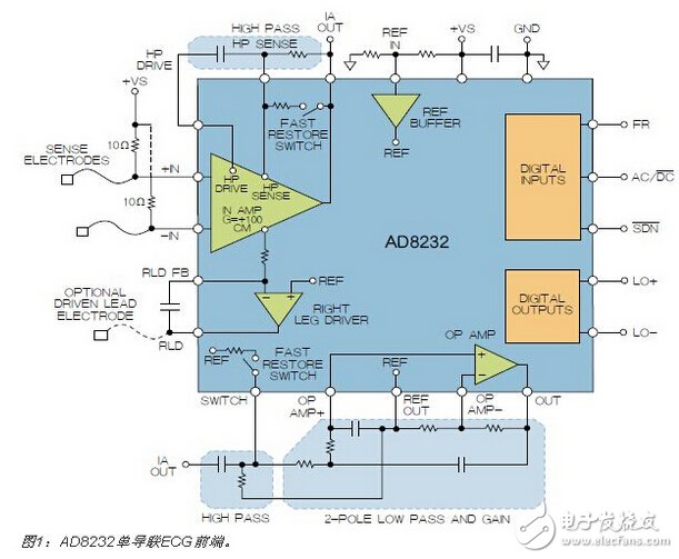
The use of single-lead ECGs in the sports world is becoming more common, using a two-electrode chest strap to measure cardiac activity. Although various ECG waveforms can be detected, most systems only measure heart rate. These chest straps are not comfortable to wear. As a result, the sports and healthcare industries are looking for alternatives, such as integrating electrodes into sweatshirts. The AD8232 single-lead heart rate monitor front end (Figure 1) was developed specifically for such low-power wearable applications. The device incorporates an instrumentation amplifier with a gain of 100V/V and a high-pass filter that blocks the offset voltage generated by the half-cell potential of the electrodes on the skin. The output buffer and low-pass filter suppress high-frequency components (EMG signals) generated by muscle activity. This low-power front-end consumes 170μA and can be used with the 16-bit on-chip meter ADuCM350 for high-performance, single-lead ECG measurements.
New method of measuring heart rate
A new trend in heart rate measurement is the Photoelectric Volume Chart (PPG), an optical technique that obtains cardiac function information without measuring bioelectrical signals. PPG is mainly used to measure blood oxygen saturation (SpO2), but it can also provide cardiac function information without bioelectrical signal measurement. With PPG technology, the heart rate monitor can be integrated into wearable devices such as watches or wristbands. This is not possible because the physiological potential signal level is extremely weak.
In an optical system, light is emitted through the surface of the skin. Photoelectric sensors measure the amount of light absorbed by red blood cells. As the heart beats, the ever-changing blood volume disperses the amount of light received. When measuring on a finger or earlobe, the best accuracy is obtained with a red or infrared source due to the considerable amount of arterial blood in these areas. However, there are few arteries above the wrist, and wrist-worn devices must detect the pulsating component through the veins and capillaries below the surface of the skin, so the green light effect is better.
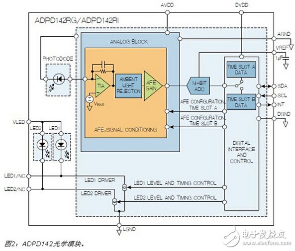
The ADPD142 optical module (Figure 2) has a complete photometric front end with integrated photosensors, current sources and LEDs. Designed to measure reflected light, the device can be used to implement PPG measurements, all packaged on a small module.
The challenge of using optical VSM
The main challenge in measuring PPG with wrist-worn devices comes from ambient light and motion-induced interference. The DC error generated by sunlight is relatively easy to eliminate, but the light emitted by fluorescent lamps and energy-saving lamps has a frequency component that causes an AC error. The analog front end uses two structures to reject interference signals from DC to 100 kHz. After the analog signal is conditioned, the 14-bit successive approximation digital-to-analog converter (ADC) digitizes the signal and sends it to the microprocessor for final post-processing via the I2C interface.
The synchronous transmit path is integrated in parallel with the optical receiver. Its independent current source drives two separate LEDs with current levels up to 250mA. The LED current is pulsed and the pulse length is in the microsecond range, thus maintaining a low average power consumption for maximum battery life.
The LED driver circuit is dynamic and ready to configure, so it is not affected by various environmental conditions, such as ambient light, the color of the wearer's skin and hair, or the sweat between the sensor and the skin, which reduces sensitivity. The configuration of the excitation LED is very convenient and can be used to build an adaptive system. All timing and synchronization are handled by the analog front end, so there is no added overhead for the system processor.
The ADPD142 is available in two versions: the ADPD142RG integrates red and green LEDs to support optical heart rate monitoring; the ADPD142RI integrates red and infrared LEDs for oxygen saturation (SpO2) measurements.
Impact of exercise
Movement can also interfere with the optical system. This may not be an issue when an optical heart rate monitor is used for sleep research, but wearing a sports watch and wristband during exercise will make it difficult to eliminate motion artifacts. The relative motion between the optical sensor (LED and photodetector) and the skin reduces the sensitivity of the optical signal. In addition, the frequency component of the motion may also be considered a heart rate measurement, so the motion must be measured and compensated. The closer the device is to the human body, the smaller the effect, but it is almost impossible to mechanically eliminate this effect.
There are several ways to measure motion. One of them is an optical method that uses multiple LED wavelengths. The common mode signal represents motion and the differential signal is used to detect heart rate. However, it is best to use a real motion sensor. Not only can this accurately measure the motion applied to the wearable device, but it can also be used to provide other functions, such as tracking activity, counting steps, or launching an application when a particular gravity is detected.
The ADXL362 is a micropower, 3-axis MEMS (Micro Electro Mechanical Systems) accelerometer that is ideal for detecting motion in battery-powered wearable applications. Its 12-bit ADC converts acceleration to digital signals with a resolution of 1-mg. Power consumption varies dynamically with sampling rate, with a power consumption of only 1.8μA at an output data rate of 100Hz and 3.0μA at 400Hz. These higher data rates are very useful for user interfaces, such as click/double click detection.
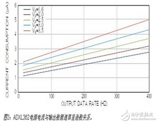
For applications that start an application when motion is detected, high-speed sampling is not required, so the data rate can be reduced to 6 Hz with an average power consumption of 300 nA. Thus, this sensor is very attractive for low power applications and implantable devices that do not easily replace the battery. The ADXL362 is available in a 3.0mm & TImes; 3.25mm package. Figure 3 shows the relationship between supply current and output data rate for different supply voltages.
Connection of sensors in the system
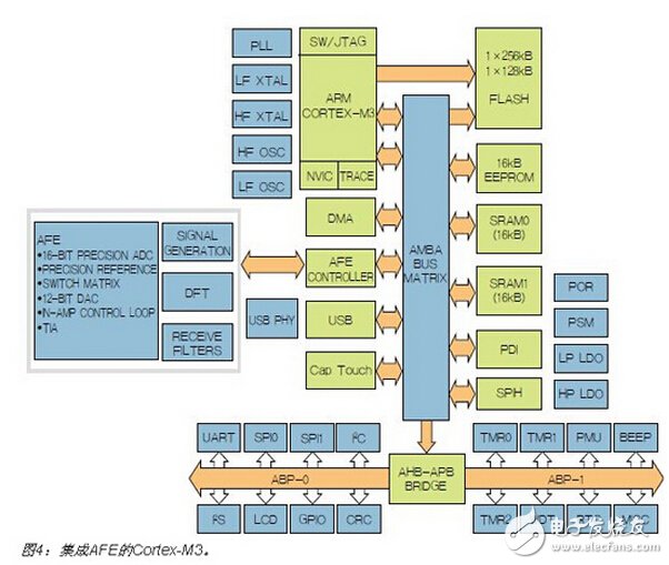
At the heart of the system is the mixed-signal on-chip meter ADuCM350, which is connected to all sensors and is responsible for running the necessary software and storing, displaying or transmitting results. The device integrates a high-performance analog front end (AFE) and a 16MHz ARM Cortex-M3 processor core, as shown in Figure 4. The combination of AFE's flexibility and microprocessor-rich features make this chip ideal for portable and wearable applications. The configurable AFE supports almost all sensors, and its programmable waveform generator can power analog sensors using either AC or DC signals. The high-performance receive signal chain conditions the sensor signals and digitizes these signals using integral nonlinearity (INL) and differential nonlinearity (DNL) with a maximum of ±1LSB of a 16-bit 160kSPS ADC. The receive signal chain supports any type of input signal, including voltage, current, constant potential, photocurrent, and complex impedance.
The AFE operates in stand-alone mode without the intervention of the Cortex-M3 processor. The programmable timing controller controls the measurement engine and the measurement results are stored in the memory via DMA. Before starting the measurement, a calibration procedure can be performed to correct the offset and drift errors in the transmit and receive signal chains. For complex impedance measurements such as blood glucose, body mass index (BMI) or tissue identification applications, the built-in DSP accelerator enables a 2048-point single-frequency discrete Fourier transform without the intervention of an M3 processor. These high-performance AFE features give the ADuCM350 an unparalleled unique advantage of other integrated solutions.
The Cortex processor supports a variety of communication ports, including I2S, USB, MIPI, and LCD display drivers (static). In addition, it includes flash memory, SRAM and EEPROM, and supports five different power modes to maximize battery life.
The ADuCM350 is designed for ultra-low power sensors with performance limitations for low speed devices. For applications requiring higher processing power, an M3 core or a Cortex-M4 processor core operating at up to 80MHz can be used.
What is the power consumption?
Power consumption has always been a key factor in portable and wearable devices. The devices presented in this article are designed for high performance, small size, and low power requirements, but integrating all of the devices (including batteries) in a small package remains a challenge. Although the new battery technology achieves a higher capacity per mm3, the battery is still larger than the electronics.
Energy harvesting reduces battery size and extends battery life. There are many energy harvesting technologies, including thermoelectric, piezoelectric, electromagnetic, and optoelectronic technologies—for wearable devices, light and heat are most suitable. Sensors typically do not generate a large amount of output power, so heat per joule should be captured and used. The ADP5090 ultra-low-power boost regulator (Figure 5) bridges the collector and battery. This highly efficient switching power supply boosts the input voltage from as low as 100mV to 3V. During cold start, the minimum input voltage required is 380mV when the battery is fully discharged, but in normal operation, if the battery is not fully drained or some power remains in the supercapacitor, any input as low as 100mV The signals can be converted to higher potentials and stored for later use.
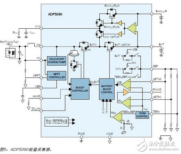
The chip is available in a tiny 3mm & TImes; 3mm package that can be programmed to support a wide range of energy harvesting sensors. With a maximum quiescent current of 250nA, it supports almost all battery technologies—from lithium-ion batteries to thin-film batteries and supercapacitors. Integrated protection circuitry ensures safe operation.
summary
This article describes some low-power products for wearable and personal health applications, but this fast-growing market is changing rapidly. ADI's technology transforms these challenging challenges into complete products and complete solutions.
- May "Test and Measurement Special" has been launched! It can be downloaded for free.
Iphone 6S Plus Battery Case quality and service:
1)From raw materials to the finished products, every process is tested and controlled professionally and strictly by our professional machines and workers.
2)All of our products are approved by CE, RoHS certificate etc.
3)Except for the Standard components, if you have special request for the components, we can customize for you.
4)Any OEM, ODM service is available.
IPhone Battery Case designed for all the iphone models,including Iphone 6 Battery Case , IPhone 6S Battery Case , Iphone 6 Plus Battery Case, Iphone 6S Battery Case , Iphone 7 Battery Case , IPhone 7 Plus Battery case, Iphone 8 Battery Case , IPhone 8 Plus Battery Case, IPhone X Battery Case .


Iphone 6S Plus Battery Case,Iphone 6S Plus Smart Battery Case,Apple Iphone 6S Plus Battery Case,Best Iphone 6S Plus Battery Case
Shenzhen Hequanqingnuo Electronic Technology Co., Ltd. , https://www.hqqnbattery.com