1 Introduction
With the increasing car penetration rate year by year, consumers have more requirements for car configuration while using cars as a means of transportation, especially higher requirements for comfort and safety. For many drivers, especially novices, reversing is undoubtedly a headache. The reversing radar can help drivers solve this problem, so more and more businesses have entered this market. Judging from the current market situation, domestic reversing radar manufacturers all use single-chip microcomputers to cooperate with peripheral op amps and phase-locked loop circuits to complete ultrasonic ranging and provide alarms. There is a lack of single-chip solutions. However, using single-chip solutions requires manufacturers to have development The ability of hardware, and the use of software control has unstable factors. If a dedicated chip can be used to realize the entire system function, for the reversing radar manufacturer, not only can it reduce development and production costs, but also greatly improve the reliability of the whole machine.
2 System Overview
2.1 System block diagram
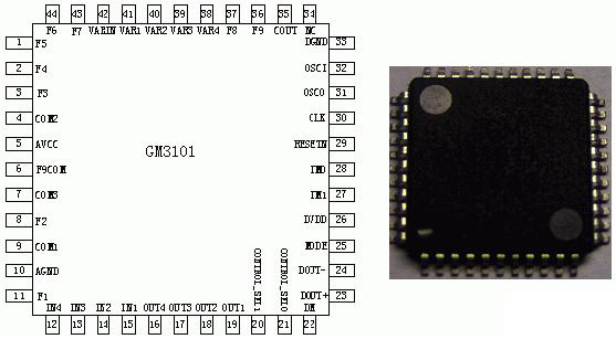
Figure 1 chip pin icon
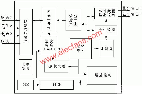
Figure 2 Block diagram of the internal structure of the system
2.2 Function Overview
The system provides 4 ultrasonic probe interfaces. After receiving the reflected signal, the danger level of the obstacle distance is judged according to the time difference between sending and receiving, and the corresponding alarm signal is output. The alarm signal is encoded and output in a two-wire differential mode. The content of the output signal includes: the danger level of the obstacle distance detected by each probe, the orientation of the nearest obstacle, the distance value of the nearest obstacle, and additional messages.
2.3 Interface protocol
The alarm signal adopts the two-wire differential serial output method, the purpose is to improve the transmission accuracy of the transmission signal in a long distance and strong interference environment. The specific format of the two-wire differential transmission is: ALOUTP outputs the actual required signal, and ALOUTN outputs the level signal opposite to ALOUTP.
2.3.1 Reversing mode
The alarm signal is output in the format of a data packet. Each data packet includes 3 bytes. The format and contents are as follows:
The first byte: the first four high-order bits of the first byte are the start flags, which are used to indicate whether the alarm data is the data in the reverse mode or the data in the pick-up mode. . The data format in reverse mode is shown in Figure 3. The lower 2 bits of the first byte are used to output additional messages. The output data indicates whether the 1 or 4 probe has entered the environmental adaptation mode, and S1 indicates whether the probe 1 has entered the environmental adaptation mode. 1 "means entering the environment adaptation mode," 0 "means the normal reversing mode; S4 means whether the probe 2 enters the environment adapting mode," 1 "means entering the environment adapting mode, and" 0 "means the normal reversing mode. The lower 4 digits SX1 and the lower 3 digits SX0 indicate the direction of the nearest obstacle, 00 indicates the direction of the probe 1, 01 indicates the direction of the probe 2, 10 indicates the direction of the probe 3, and 11 indicates the direction of the probe 4.

Figure 3 First byte data format
The second byte: As shown in Figure 4, SXA and SXB represent the hazard level of the obstacle detected by the X probe. The hazard level is divided into four levels: safety, warning, danger, and parking. Use 00, 01, 10, 11 said. For example, the second byte of data is "10010000", indicating that the first probe detects a dangerous state, the second probe detects a warning state, and the third and fourth probes are in a safe state.

Figure 4 Second byte data format
The third byte: the third byte outputs the distance value of the nearest obstacle, the data format is shown in Figure 5, DA1DA0 represents the first digit of the distance of the nearest obstacle, according to BCD encoding, the maximum value is 3; DB0 ~ DB3 represents The second data of the closest obstacle distance is coded according to BCD, the maximum value is 9; DC0 represents the third data, 0 represents 0, 1 represents 5.

Figure 5 Third byte data format
[page_break]
2.3.2 Anti-pickup mode
In the anti-pickup mode, the output data packet also includes 3 bytes, but only the first byte is valid data, and the last two bytes are invalid, fixed to '0x00'. The data format of the first byte of the data packet is shown in Figure 6. The upper four bits are the start flag, which is used to indicate whether the alarm data is data in the reverse mode or anti-pickup mode. The reverse mode is "0101" The grilled car mode is "1010". The lower four digits indicate azimuth. The SX bit of 1 indicates that the No. X probe has detected a close obstacle, and the SX of 0 indicates that no close obstacle has been detected.

Figure 6 Anti-pickup car mode alarm data format
3 Intelligent principle
3.1 Anti-sound diffraction treatment
Due to the characteristics of acoustic wave transmission, the acoustic wave will return to the probe and be detected without being reflected by the actual object, causing the processor to think that it is actually transmitting and receiving the signal, which directly leads to false alarms. However, the interference intensity of sound wave diffraction is difficult to achieve the effective ultrasonic intensity reflected by the actual object, so it can be judged by identification. Once the hardware determines that the received ultrasonic signal is the signal returned by the sound wave diffraction, it automatically ignores the result, and the chip continues to wait for a valid reflected wave within a fixed time â–³ T. .
3.2 Intelligent recognition processing
Small objects on the ground, such as bricks, stones, and fruits, will cause the reflection of ultrasonic waves and be detected by the probe. These objects do not affect the vehicle's reverse operation, so it is actually a false alarm. Therefore, the hardware must deal with this situation to improve the accuracy of the alarm.
The intelligent recognition process can be judged by the amplitude of the ultrasonic waves reflected by objects of different sizes. So once it is determined how big the object will not affect the operation of reversing, you can clearly measure the amplitude of the ultrasonic wave generated by the object at different distances and the level level after conversion. The processor can simulate or digitally according to the results of the experimental test. Partially process and ignore the corresponding received signal as required. As with the anti-sound wave diffraction processing, after ignoring the invalid reflected wave, the hardware should continue to wait for whether there is an effective reflected wave within a fixed time ΔT.
3.3 Environmental adaptation treatment
There will be false alarms caused by environmental impacts when vehicles are reversing into an alley or parking spaces in parking lots where other vehicles have been parked on both sides. In this case, during most of the reversing process, the closest detection distance and orientation are on both sides of the body (ultrasound reflection from the wall or vehicles on both sides), but the driver can grasp the vehicles on both sides through the mirrors on both sides. The driver is concerned about obstacles behind the body. So the processor should be able to recognize and adapt in this environment.
The solution is to record and count the distances emitted by the objects on both sides of the body. When it is found that probe 1 and probe 4, or one of them, the distance detected in 6 alarm cycles is relatively constant, or the change range is small, then it is considered In the above environment. Therefore, after sending the corresponding message, the processor no longer outputs the detection information of the corresponding probe, and only responds to the detection information of probe two and probe three. However, if the detection distance of probe one and probe four changes beyond the set value (± △ L meters), it will immediately return to the normal detection state machine mode, and the distance between the two sides or one side will be constant again and then go to the environment adaptation mode under. At the same time, the environment adaptation mode also has a limit setting value (0.5 meters), that is, when the constant distance is less than 0.5 meters, the processor returns to the normal detection mode and outputs an alarm message to the detection information of the probe.
3.4 Anti-ground fixed sound wave reflection treatment
Because the height and slope of the chassis and rear bumper of various vehicles are different, and the types of probes used by various reversing radar manufacturers are different, such as the wide range of single-angle probes, there is a possibility that ultrasonic waves are emitted to the ground After the fixed reflection situation, the processor must adapt to and recognize a fixed distance of interference.
The processing method is: after each start-up operation, it is detected that the distance values ​​of the obstacles received by the four probes within 6 alarm cycles are consistent and constant (the error is allowed to be within ± △ L meters), then the distance is regarded as Ground reflection interference will no longer respond to processing in the future, but wait for other valid ultrasonic transmission signals within a set period of time.
4 hardware implementation
4.1 code implementation
// + FHDR ============================================== =================
// Copyright 2005, UESTC, All rights reserved.
// File Name: alarm_deal.v
// Author: Yangbing
// Release History
// Version Date Author DescripTIon
// 1.0 20/05/2005 iniTIal version
//-FHDR ============================================== ================
`TImescale 1ns / 10ps
module alarm_deal (clk, resetn, mode, dm, pulse_out, pulse_back, ch_sel, mux_enable,
alarm_out, alarm_outn);
// ==================================================== ====================
// input ports declaraTIon
// ==================================================== ====================
........................................................................................................................
.....................................................................................................................
// ====================== end module ======================== ============
endmodule
// ================= alarm_deal verilog file end =========================== ==
4.2 Circuit structure
This system uses the 0.5u mix signal process. With the support of the working platform of Chengdu Guoteng Microelectronics Co., Ltd., it has successfully completed comprehensive verification and layout design work. The integrated circuit structure is shown in Figure 7:

Figure 7 circuit structure

Figure 8 layout structure
4.3 Layout design
The layout design uses the 0.5u mix signal process, and the layout structure is shown in Figure 8.
5 Application system design

Figure 9 Typical application
The core of this typical application system (Figure 9) is composed of the data processing part with the reversing radar main control chip GM3101 as the core and the data display part with the single chip as the core. After testing, it fully meets the requirements of high-end products on the market, even in terms of display distance, display sensitivity, and system stability. Compared with other reversing radar systems on the market, it has the following advantages:
(1) Anti-interference and reliability
The traditional reversing radar uses a single-chip microcomputer based on RAM and ROM structure, so it can not be compared with pure hardware ASIC chips in terms of electromagnetic interference resistance and stability. The GM series of reversing radar special chips work reliably and stably without crashing.
(2) Simple design and easy production
The traditional reversing radar design is complicated, the devices are numerous, the possibility of failure is greater, and programming is required, the production and debugging are troublesome, the performance of the separated components is large, and the overall indicators are not easy to unify. The design and application of GM series reversing radar products are very simple, only need an external probe and a small amount of resistance and capacitance to work, reducing the amount of development, while significantly reducing the area and size of the host, can achieve the traditional reversing radar size 1/3.
(3) Automotive-level work indicators
GM series reversing radar products are designed for automotive-grade working environment indicators, which are much higher than the civilian-grade single-chip microcomputer, which fully meets and adapts to the working conditions in the car.
(4) Reliability of data communication
The differential communication mode is adopted between GM3101 and its supporting display part, which has extremely strong anti-interference and reliability, which cannot be realized by single chip microcomputer.
(5) Prevent the interference of sound wave diffraction
Due to the processing power of the single-chip microcomputer, the traditional reversing radar is difficult to deal with the interference of the sound wave diffraction on the detection. The GM series of reversing radar products can completely filter out the interference of the sound wave diffraction, making the detection more reliable and accurate.
(6) Intelligent recognition function
Since any object reflects sound waves, the reversing radar can detect the distance of the object. In actual reversing applications, many objects that are too small, such as fruits, softballs, etc., will be alarmed by the parking sensor as obstacles, but these objects that are too small do not affect the normal reversing of the vehicle, so the GM3101 chip can be intelligently identified The physical properties and size of the object, and then the alarm processing, to avoid the above-mentioned unnecessary alarm.
(7) Prevent reflection interference from fixed ground
The height of the rear bumper of various vehicles and the inclination of the vertical plane of the rear are inconsistent. Sometimes the installation angle of the probe is too low, and the sound wave reflects on the uneven ground, which makes the reversing radar mistakenly consider it as an effective obstacle and alarm. The GM3101 chip can automatically adapt to the reflection interference caused by the ground and avoid false alarms.
(8) Environmental intelligence adaptation
When the vehicle enters the lane or the parking space where the vehicle has been parked on both sides is reversed, since the distance between the two sides of the vehicle is shorter than the distance behind the vehicle for a relatively long time, the ordinary reversing radar can only respond to the detection of the shortest distance and let the driver Unable to understand the real situation behind the car. The GM3101 can intelligently determine the parking area, so that the reversing radar can focus on the situation behind the car that the driver is more concerned about, and it will not ignore the detection on both sides.
6 Summary
Through detailed analysis and design of the electronic reversing radar system, the interference of sound wave diffraction, environment adaptation, intelligent recognition processing, and alarm output selection corresponding to different application situations have been successfully achieved. The system can effectively prevent the unstable factors of software control, not only can reduce the development and production costs of reversing radar production, but also greatly improve the reliability of the whole machine.
Heater is a combination of fans, motors and air heaters combined unit. Applicable to all types of workshops, when the air is free of dust and flammable or explosive gas, can be used as a circulating air heating. Heater can be used independently as a heating, generally used to supplement the lack of heat sink parts or the use of radiators as the duty of heating, the remaining heat load borne by the heater.
(1) horizontal blower: indoor air from the side of the inhalation, the heat exchanger after the heat, the horizontal direction. The jet has a certain range, so that the heating zone is fully blended, the temperature is evenly mixed.
(2) top blower fan: axial fan placed in the bottom of the unit, the air from the side of the heater into the air through the standing heat exchanger, and then sent down. In order to make the jet face to be discharged downward, a guide vane for diffusion is provided at the outlet of the fan.
(3) floor heaters: such units of the large amount of air, send hot air range far, can afford a larger area of heating. When running, the noise is large. Applicable to the factory building heating.
The advantage of heater heating is [2]:
(1) single machine heat supply, in the same heat load, the number of end devices used less;
(2) small heaters can be hanging, do not take up the building area, large heaters floor installation, covers an area of limited;
(3) start heating up fast.
Fan Heater
Fan Heater, Portable Electric PTC Fan Heater, Square Nice Electric Heater, Desktop Portable Electric Fan Heater
Ningbo APG Machine(appliance)Co.,Ltd , http://www.apgelectrical.com