Video inspection systems have been widely used in commercial and industrial fields. Cameras-from cheap and low-resolution products in black-and-white closed-circuit television (CCTV) systems to advanced and high-resolution products in digital video systems-are used for everything from product inspection, traffic supervision to real-time face recognition Application occasions.
The video itself carries a lot of data, which makes the signal processing and data storage tasks quite complicated. By discarding useless information and passing only important parts of the picture, the video inspection system can be simplified, saving memory and computing cycles. Figure 1 shows the components of a typical system.
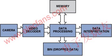
Figure 1: Simplified video inspection data flow.
This article will explain how to extract useful data to minimize processing requirements, memory capacity, and DSP utilization, and introduce how the special features of ADI ’s video decoder can simplify video algorithms and speed up the development of video inspection systems.
Example 1: Count and inspect objects
Imagine that a wide conveyor belt is quickly transferring many products, and the large number of products makes manual counting very difficult. In addition to automating counting tasks, cameras can also be used to monitor product quality. This can be achieved by modifying the simple counting algorithm to focus it on specific details and flaws.
Storing all video data requires a lot of memory, and processing a lot of data also requires a lot of hardware resources and processing power. Therefore, when inspecting the products on the conveyor belt, the system will not collect the entire picture data into the memory, but will find the details of interest from the large amount of data and discard as much useless data as possible.
In most cases, gray-scale pictures carry enough information, so RGB signals can be converted into (luminance only) Y signals, and chrominance information is discarded. Then use the edge detection method to check the content in the monochrome picture to find the products on the conveyor belt, and then compare their shapes with the template to determine whether the product is normal.
The edge detection algorithm-only requires a few lines of active video and a small amount of memory-can find the discontinuity of the brightness of adjacent pixels by calculating the first and second derivatives of the active picture, see "Digital Image" by Bernd Jähne Processing ". In practical applications, edge detection can be achieved by extracting information using matrix calculation methods, such as the Sobel matrix operator. In FPGA (Field Programmable Gate Array) implementation, such edge detection in pixels can provide satisfactory results. The article "A proposed FPGA Based Architecture for Sobel Edge DetecTIon Operator" written by Tanvir A. Abbasi and Mohm Usaid Abbasi introduces a simple FPGA implementation scheme. The noise can also be eliminated by adding a Gaussian two-dimensional filter. For details, see "Hardware AcceleraTIon of Edge DetecTIon Algorithm on FPGAs" by Mathukumar Venkatesan and Daggu Venkateshwar Rao. This article introduces a successful implementation of a detector similar to the Canny edge detector.
There are several other optimization algorithms that can be used to improve picture quality, but these algorithms all occupy valuable resources in FPGA design. However, some integrated circuit (IC) video decoders have integrated practical preprocessing algorithms or filters, so choosing such an IC can save FPGA resources. For example, the ADV7802 video decoder includes the Luminance Transient Improvement (LTI) and Chroma Transient Improvement (CTI) modules. These modules improve picture quality by improving the sharpness of brightness and chromaticity changes, and use adaptive peaking and non-linear methods-without adding noise or introducing defects-very useful in the edge detection process. In addition, brightness shaping and other built-in input filters can eliminate high-frequency noise from the signal source-focus on the signal and ignore the accidental noise.
Figure 2: LTI / CTI operation diagram.
Edge detection provides information on the changes in the edge of the object, not the entire picture of the object. The amount of data can be reduced from 3 × 8 bits / pixel (bpp) to 1bpp, thereby saving a lot of memory space:
640 pixels × 480 pixels = 307,200 bits (at 1bpp)
800 pixels × 600 pixels = 480,000 bits (at 1bpp)
1024 pixels × 768 pixels = 786,432 bits (at 1bpp)
1280 pixels × 720 pixels = 921,600 bits (at 1bpp)
By converting RGB to Y, storing only a few lines of active video in memory, and using FPGA algorithms, we can detect objects and observe their shapes. Once we know the position of these objects on the moving conveyor belt, we can estimate their movement and collect color or other information from the next frame to ensure that the minimum memory space is used. This process involves:
Edge detection
Store information
Predict the next position xn + 1
Extract information from preset product location areas
Example 2: Detecting motion and quality
The robot can find targets within a certain distance and within a limited range. Ultrasound can be used in some applications; but if the surface of the object absorbs ultrasound or the target is behind glass, video can be used. The focal length of the camera is set on nearby objects. Objects in the close range will have clear edges, while background objects outside the range will only have blurred edges (Figure 3).
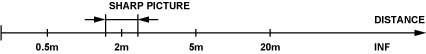
Figure 3: Focal length-narrow depth of field.
Edge detection can be used to distinguish objects within the target distance because they are the only objects with clear edges. Objects in the background will be blurry enough to fail the edge detection test. This edge detection process will produce a binary bitmap, where 1 indicates that an edge has been detected and 0 indicates that no edge has been detected. The position (x, y) of each detected edge pixel can be substituted into Equation 1 to approximate the midpoint of the isolated object:
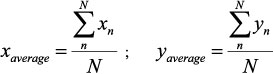
(1)
Where xn is the x-axis position of edge pixel n, yn is the y-axis position of edge pixel n, and N is the number of detected edge pixels.
Once the position of the object and its edges are known, we can try to track it. The key is to correctly extract the object from the picture, convert its edge into a contour, and then use it to determine whether the object is moving toward the camera. The method is to check the average distance of the pixel from the center of the object to determine whether the object size is changing, as shown in Equation Show:
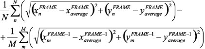
(2)
N is the number of edge pixels in the FRAME frame, and M is the number of edge pixels in the FRAME-1 frame. Focusing on the horizontal axis gives Equation 3:
(3)
When the object moves toward the camera (the pixels extend outward from the center of the object), the value of this formula is positive. A negative value means that the object is moving away from the camera, as shown in Figure 4.
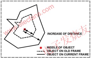
Figure 4: Frame changes of moving objects.
Please note that the object must be within the focal length of the camera. By modifying the algorithm we can actively change the focal length to scan a larger area. Once an object is detected, it can be segmented, processed, and tracked.
As the complexity of the video increases, it will become more difficult to track objects, especially textured objects and objects that lose sharpness due to excessive movement speed. Jianbo Shi's "Good Features to Track" article introduces some tracking algorithms. When the object loses sharpness, edge detection will fail. In this case, use complex correlation techniques (such as module matching)-used to estimate motion-or use the book "Video Processing and Communications" co-authored by Yao Wang, Jörn Ostermann, and Ya-Qin Zhang. The other methods can still complete the tracking.
Since the camera provides a continuous data stream, it can judge its acceleration and other parameters by tracking the object. However, high-quality video sequences must be used to obtain good video analysis results. When detecting edges by analyzing adjacent pixels, progressive video has better resolution than low-quality interlaced PAL or NTSC signals. The ADV7401 and ADV7403 video decoders can accept various video standards, including progressive mode. The two devices can digitally process video signals up to 140MHz, and can handle standard definition, enhanced definition and high-definition component signals, CVBS and graphics. In addition, they also support non-standard video modes, allowing the use of less popular standards such as STANAG. The flexible pixel output bus allows processing of 4: 2: 2, 4: 4: 4 YcbCr or 4: 4: 4 RGB format data. Non-standard video formats can achieve a specific horizontal width by oversampling or undersampling. For details, see application note AN-0978, “Component Processor Nonstandard Video Formatsâ€.
The built-in color space converter (CSC) shown in Figure 5 can convert color spaces to meet user requirements (Equation 4, where A1 ... A4, B1 ... B4, C1 ... C4 are all adjustable CSC parameters). YPrPb or RGB input signals can be converted to other formats using the configurable matrix conversion function. For example, converting RGB to YCbCr allows chroma information (Cb, Cr) to be discarded, and edge detection can be simplified by using monochrome pictures.
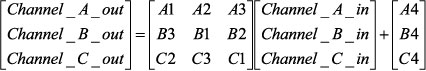
(4)
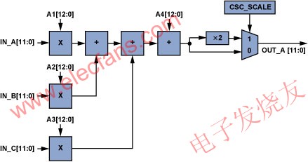
Figure 5: A single CSC channel (ADV7403).
CSC is very useful. When the input is RGB or YCbCr, the color information can be simply converted using a color space matrix. Figure 6 shows a YUV color space similar to YCbCr.
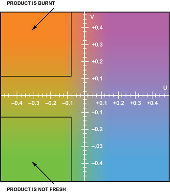
Figure 6: The YUV color space used in product quality assessment can be used to detect (for example) whether the product is burnt or deteriorated. Y (brightness) is a constant.
As shown in Figure 6, color (or YPrPb value) helps to detect product quality, such as whether it is burnt or deteriorated. Color space conversion is necessary in video processing and when connecting to ICs that use other standards. The ADV7401 / ADV7403 has a built-in input multiplexer to easily switch the video source. This feature is very useful when switching from a stopped conveyor to another running conveyor.
Example 3: Adjust the white balance and color balance in the video check
Developing a video system that extracts objects from pictures requires hard work, because slight changes in light angle or intensity can affect the inspection results. Video engineers can use the gain and offset adjustment functions of the ADV7401 / ADV7403 to adjust brightness and contrast by adding two very short reference stripes (one dark and one bright) to the conveyor belt. The offset and gain of the ADV7401 / ADV7403 are adjusted to obtain comparable values, allowing the system to compensate for changes in light color, angle, and intensity.
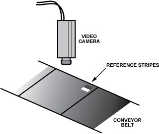
Figure 7: Add small reference stripes in the visible area.
The algorithm for adjusting the correct white balance is very simple. First, the RGB (or YCbCr) value of the reference stripe is obtained. Then, to compensate for changes in light, you can simply change the offset and gain of the device to the same value as the reference value. This algorithm can be used to:
Obtain the RGB (or YCbCr) value of dark stripes
Adjust the offset to match the ideal RGB (or YCbCr) value of dark stripes
Obtain the RGB (or YCbCr) value of bright stripes
Adjust the gain to match the ideal RGB (or YCbCr) value of bright stripes
To improve accuracy, repeat steps 2 and 4
This process is especially important during system development because it provides the correct offset (brightness) and gain (contrast)-even when the light is too strong or too weak, as shown in Figure 8. The offset and gain registers can be accessed via the I2C bus, enabling fast adaptation.
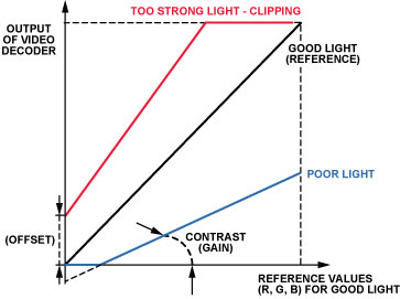
Figure 8: Adjusting the offset and gain to compensate for changes in ambient light.
Color can also be used for reference stripes. This compensation is similar to white balance and is widely used. However, although white balance is more consistent with human perception, color correction can compensate for changes caused by different lighting. Although the algorithm is similar, the additional offset will cause dark colors to look unnatural. The ADV7401 / ADV7403 color space conversion, flexible output pixel port, and offset and gain adjustment registers allow engineers to quickly develop algorithms using the data already prepared. As mentioned earlier, it is important to reduce the amount of data required for video processing, and try to avoid using advanced algorithms for simple videos. The ADV7401 / ADV7403 evaluation board with easy-to-access pixel ports is available, and it can speed up the launch of new designs. Simply insert the video capture board into the pixel port of this evaluation board to capture video data (Figure 9).
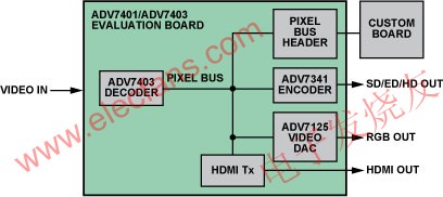
Figure 9: The pixel bus on the ADV7401 / ADV7403 evaluation board.
The video encoder, video DAC and AD9889B HDMI transmitter are connected to the same pixel bus, allowing the current picture to be checked at the second output port. ADI's video decoder contains the modules required for video processing, which can provide robust performance and stable pictures.
Conclusion
Video cameras can bring many benefits in industrial applications. This is especially important when moving objects must be classified, tracked or recorded. Video technology and real-time processing functions with a highly integrated video decoder can be used to efficiently analyze objects on moving conveyor belts or sort mixed products on conveyor belts.
Strip light with both RGB colorful light and warm light, the length of the strip light is 2 meters, 60pcs LED lamp beads inside are high-quality and energy-saving , the light source is stable without strobe.
The installation is very simple, just need to peel off the 3M glue on the back, you can paste and decorate any place.
With the exclusive designed 2.4G remote controller, get you off the switch and turn on / off the lights anywhere, one remote controller can set 4 groups, each group is recommended to match up 8pcs bulbs, one remote controller can max control 32 bulbs. This remote controller is suitable for all 2.4G version of RGBW products under [linkuphome".

The remote control uses colorful touch buttons, the color touch buttons are comfortable and sensitive. The remote controller has the functions of grouping, lighting, brightness adjustment, color light automatic cycle mode, three cycle speeds can be choosed. The wireless control distance is around 20 meters. Low power consumption makes the remote controller only need 4pcs AA batteries, but can be used for two years.
Product Parameters
Control Qty: 1-48 pcs
Control distance: 20m
Material: Polyurethane with 3M back adhesive
Working Voltage: 100-240V
Frequency: 50/60Hz
Lamp Color: RGB+Warm White
Color Temperature: 3000K
Meters: 2 Meters
LED Power: 7W
Power Adapter: 12V/2A
Product Specification: 30pcs LED beads/M, 2 M/root, total 60pcs LED beads.
(3pcs strip lights can be connected, max to 6 meters.Need customized. Pls inform in advance if needed)
Warranty: 2 Years
Color box size: 20*18*4.8cm
G.W. of Unit: 0.29kg
N.W. of Unit: 0.21kg
Discreption: 2.4GRF Wireless RGB Remote Controller
Product dimension: 105mm *33mm,
Product Net Weight: 150g
Material: ABS & Metal
Battery: 4*AA battery (not included)
Working Power: 6V
Standby Power: 3 mW
Frequency Band: 2400-2483.5MHz/2.4GHz
Control Distance: 20m
Control bulb qty: 1-32 pcs
Packing: Each in a color box
Warranty: 1 Year
Color box size: 16.7*14.7*4.5cm
G.W. of Unit: 0.22kg
N.W. of Unit: 0.15kg
Strip Light With Remote Control
Strip Light With Remote Control,Remote Control LED Lights Battery Powered,Remote Control Strip Light,Remote Control Flashing Strip Light
Ningbo Homey Photoelectric Technology. Co., Ltd , https://www.linkuphome.com