In recent years, urban nightscape lighting construction is booming, and the floodlighting of the facade of the building (structure) is increasingly being applied to all aspects of society. Below I briefly introduce two kinds of calculations for floodlighting. method.
First, the light method <br> From the lighting design principle, lighting a facade and lighting a horizontal plane is the same. Therefore, for the sake of understanding and convenience of description, the lighting level is taken as an example.
To illuminate a square or rectangular area, there are generally three ways:
1. Mount the lights on the four corners;
2. Install lights on the opposite sides of each other;
3. Install the lamp in the middle of one side.
Of the three methods, the first one is the best; the second light utilization is slightly lower, but the light pole is reduced; the third method is the worst, and can not give good illumination to the far corners and corners. Below we discuss a specific design example.
The face to be photographed is: 54.9 meters & #215; 54.9 meters, the required illumination is 54 lux.
1. If the height and spacing of the pole are only illuminated from one side, the height of the pole should be about half of the area to be illuminated. In this way, the spotlight can be aimed at the opposite side, or within 2 times the height of the pole. At this time, there is better uniformity and reasonable utilization. For large areas, the spacing between the poles should be 4 times the height of the poles, as each projector can effectively illuminate the area of ​​the height of the pole twice. For a 54.9× 54.9 meter surface, a 27.4 meter pole height can be used if illuminated from one side. If it is illuminated from both sides, it is better to take a height of 13.7 meters. At this time, the light can be aimed at 2 times the height of the pole, that is, 27.4 meters, just at the center of the illuminated surface. If the floodlights are mounted on the four corners, the height of the pole is still 13.7 meters, still aiming at 27.4 meters, so that the central part of the face will be illuminated by the lights on the four corners. The two-side lighting scheme is adopted, the height of the pole is 13.7 meters, and two lamps are mounted on each pole.
2. Selection of lamp type and lamp In various kinds of light sources, high-pressure sodium lamp has high light efficiency and long service life. When the color requirement is not too high, it can be used. In today's case, it is preferable to use a symmetrical illuminator because the luminaire with a wider horizontal beam can better cover the illuminated surface than a circular beam luminaire.
3. Calculate the calculation formula as: N=(E×S)/(F1×CU×LLF) (1)
Where: N is the number of required lamps E is the illuminance value required to be maintained S is the illuminated area F1 is the luminous flux of one lamp CU is the utilization coefficient LLF is the optical loss factor
The specific calculation steps are as follows:
(1) Estimation of optical loss factor - The optical loss factor is caused by two factors, one is the light decay LLD of the lamp, and the other is the dimming LDD caused by the ash accumulation. The LLD and LDD values ​​of various lamps and lamps may be specified in the manufacturer's product manual or may be found in the relevant manual.
The LWD of the 1000W high pressure sodium lamp is 0.9, and the LDD of the sealed lamp is 0.95, then LLF=LLD× LDD=0.9× 0.95=0.855.
(2) Calculate the area of ​​the illuminated surface S
S=54.9×54.9=3014m2
(3) Estimating the utilization factor CU after the combination of lamps and lamps
The CU is defined as the ratio of the light that contributes to the contrast on the illumination surface and the luminous flux of the lamp. Note that when it is not the ratio of the luminous flux to the lamp but to the luminous flux of the beam, it is called the "beam utilization factor". In this example, CU = 0.4.
(4) Calculate the number of required floodlights N
If a 1000W high pressure sodium lamp is used, the luminous flux per lamp: F1 = 140000 lumens. Substituting the relevant data into (1) is calculated: N = (54 lux & # 215; 3014 square meters) / (140000 lumens & # 215; 0.4 & # 215; 0.855) = 3.4 that 3.4 lamps can be used. We now use 4 lights, of course, to meet the design requirements.
Second, point-by-point calculation
If the case of floodlighting as shown. In the figure, A is a rectangular illuminated surface, and the installation height of the floodlight S is MH (the light pole is high). It is now desired to calculate the horizontal illuminance value produced by the lamp at each point of the illuminated surface A. For the sake of simplicity, the coordinate system is taken as shown.
The horizontal illumination produced by the floodlight at P(c,y) is Ep=I (H, V)cos3g/(MH)2 (2)
Where: MH is the installation height of the lamp a is the angle between the optical axis of the lamp and the lamp post. The vertical angle H of the beam I (H, V) is the horizontal angle g of the beam I (H, V) is the beam I (H, V The angle I (H, V) with the light pole is the light intensity that is directed toward the point P (ie, the H, V direction).
It can be seen from the figure that b=arctg(y/MH) (3)
V=ba
When V is positive, it means the upper half beam; when V is negative, it means the lower half beam. And H=arctg(ccosb/MH)
From the figure, it is not difficult to see cosg=MH/SP, cosb=MH/SN, cosH=SN/SP. Therefore cosg=cosb.cosH. Therefore, (2) can also be written as: Ep = I (H, V). cos3b.cos3H / (MH) 2
For each point on the illuminated surface, b, V, H can be obtained from (3), (4), (5) by its (c, y) value, and I(H, V) can be found from the luminosity database of the luminaire. ), so that the illuminance distribution produced by the luminaire on the surface A can be found. The points of the same illuminance on the surface are connected to form an iso-illuminance curve.
Third, the uniformity of illumination <br> No matter how carefully designed, no illumination on the illuminated surface is absolutely uniform. As long as the ratio of maximum illumination to minimum illumination is less than 10:1, the system is considered to be uniform. In order to better describe the uniformity of illumination, a Um is introduced, in which Um=Emin/E is defined, Emin is the minimum illumination, and E is the average illumination. Obviously, the larger the Um, the more uniform the illumination. Unless there are special requirements, generally Um ≥ 1/3. For the stereo illumination of a building, illumination is not required to be uniform in most cases, and illumination is not intentionally made uneven for artistic effects. There are other methods for the calculation of floodlighting design, such as drawing method, illuminance curve composition method, etc., which are not introduced here.
Fourth, the conclusion <br> For the two methods described in this article, the reader can be applied in different situations. The light-pass method can be used to estimate the amount of light used for illumination, or for applications where the illumination of the illuminated surface is not critical. The point-by-point calculation method can accurately calculate the illumination distribution on the illuminated surface, and with the aid of the computer, the optimal scheme of the lighting design can be determined, such as the lamp type, power, lamp, model, installation height, aiming point. Location and more.
USB Type-C Is Commonly Referred To As USB-C And Is A 24-Pin, Fully Reversible Plug USB Connector System That Can Transfer Data And Charge.
A Full-Featured USB-C Cable That Supports USB 3.1 Gen 2 Can Handle Data Rates Up To 10 Gbit / S Over Full Duplex. Type-C Converter Is Marked With The SuperSpeed + (SuperSpeed 10 Gbit / S) Flag. There Are Some Cables That Can Only Support Up To 480 Mbit / S Data Rate For USB 2.0.
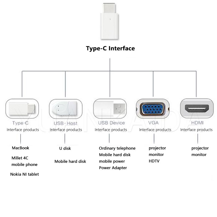
USB Type-C Biggest Feature Is The Access Is No Longer Positive And Negative, The Maximum Support USB 3.1 Standard, Backward Compatible With USB 2.0. Type-C Converter Will Power, USB Data Transmission, Display Port, HDMI And VGA Five Functions Set In One, So Type-C Interface Can Be Transferred Into Any Of The Five Kinds Of Interfaces Or Arbitrary Combination.
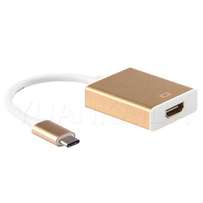
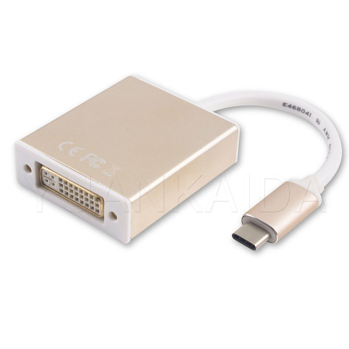
Support Type C to DVI Converter, Type C to HDMI Converter, Type C to VGA Converter, Type C Converter , Type C to DP Converter And Other Products

Type-C Converter

Type-C TO HDMI Adapter

Type-C to DVI Adapter
Type C Converter
Type C to DVI Converter,Type C to HDMI Converter,Type C to VGA Converter,Type C Converter,Type C to DP Converter
Shenzhen JunYuanJie Electronic Technology Co., Ltd. , http://www.usb3c.com