0 Preface
The recording and playback of voice by the MCU and the FPGA can have rich interface resources and computing power. In view of the excessive storage redundancy value of the PCM and the quantization noise problem of the DPCM, ADPCM becomes a good compression algorithm. At the same time, in order to have high common mode rejection ratio, low distortion, high power and high input impedance, this paper uses instrumentation amplifier, stereo power amplification and control chip, combined with ADPCM coding, designed and realized with fast acquisition speed and long storage time. A digital voice storage and playback system with good voice playback quality.
1 system design block diagram
The system mainly includes a part of the acquisition, processing and voice playback module. For the acquisition module, the voice input by the microphone or the earphone is generally pre-processed by preamplification and low-pass filtering to complete the A/D conversion. For the speech processing module, the ADPCM encoding and the FFT operation are performed, and the digitized speech can be stored in an external medium. For the playback module, the stored voice content can be extracted, and the playback function is completed by decoding, D/A conversion, and finally driving the speaker. The overall block diagram of the system is shown in Figure 1.
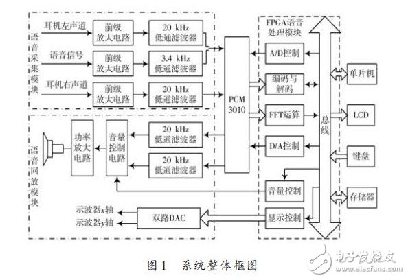
The stereo ADC and stereo DAC components are integrated inside the chip PCM3010. The stereo volume is adjusted by the stereo volume control chip PGA3010, and finally the power amplifier drives the speaker to complete the voice playback function. At the same time, the spectrum of the speech signal can be displayed on the oscilloscope in real time by performing short-time Fourier transform on the sampled data inside the FPGA.
2 theoretical analysis and calculation
2.1 Theoretical Analysis of ADPCM Coding
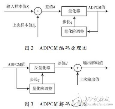
The processing of ADPCM is to encode the difference between two adjacent samples, and use the adaptive idea to change the size of the quantization step. The ADPCM coding method combines DCM and ADM, which is actually an adaptive direction improvement of the differential algorithm. There is a difference between the input signal Si and the adaptive output value Sp, and the difference is quantized according to the adaptive quantization step d, and the ADPCM four-bit quantization code I is output. For the quantization code I, the quantization step d is recalculated. Its texture diagram is shown in Figure 2.
On the other hand, for the quantization code I, it is sent to the inverse quantizer, and the difference is determined according to the calculated step d, a new decoded value is generated, and the next round of speech coding is performed. The texture diagram is shown in Figure 3.
With the encoding of ADPCM, a compression ratio of 1/6 can be achieved. That is to say, for 24 b of sampled data, the storage rate of 4 b can be achieved, which can greatly extend the storage time. When the sampling rate is 46 kHz, the data transfer rate is 184 Kb/s. Since the external memory BQ4015 is 512 & TImes; 8 Kb, the maximum time that can be stored is 22 s. When the sampling rate is 8 kHz, it can be stored. The maximum time is 128 s.
2.2 Signal to noise ratio calculation
It is generally believed that the speech frequency of the call generally does not exceed 3.4 kHz, so the low-pass filter selects 3.4 kHz as its cut-off frequency, while ensuring that the A/D sampling frequency is higher than 8 kHz, according to the Nyquist law, the speech quantization can be satisfied. No loss. For headphone channel sounds, the frequency range is 20 Hz~20 kHz, so the above filters and A/D sampling frequency can also meet the requirements. According to the following signal to noise ratio (unit: dB) formula:
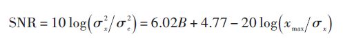
If the speech signal is assumed to follow the Laplacian distribution, then xmax = 4σx.
So you can calculate:

It shows that the contribution of each bit word length in the quantizer to the signal-to-noise ratio is about 6 dB. The PCM3010 with 24 b A/D converter can theoretically achieve a signal-to-noise ratio of 137 dB.
2.3 Pre-emphasis processing
In order to improve the voice quality, the collected voice is generally pre-emphasized. The high frequency portion of the signal is boosted while the signal is flatter. The processing generally falls at -6 dB/octave in the high frequency band, and a pre-emphasis digital filter with 6 dB/octave boosting high frequency characteristics is implemented inside the FPGA. Select the first-order high-pass filter whose characteristic function is:

In the formula, the value of u is 0.94~0.97. Of course, after the signal processing, it is necessary to de-emphasize the voice signal of the copy.
Product Description
SPD Surge Protective Device,Lightning Surge Protector
Surge Protection Device (SPD)
It is a device used to limiting instant surge voltage and discharge surge current, it at least including a non-linear component.
Surge protective Device Model Selection
With the impact of international information flow, the rapid development of microelectronic science and technology, communication, computer and automatic control technology, make the building start to go for high quality, high functional area, formed a new building style-intelligent building. As inside the intelligent building there are lot of information system, <<Building lightning protection design norm>> GB50057-94(2002 vision)(hereafter brief as <<lightning protection norm>>) put forward the relative requirement to install the surge protective device, to ensure the information system safely and stable running.
SPD essentially is a equipotential connection material, its model selection is according to the different lightning protection area, different lightning electromagnetic pulse critical and different equipotential connection position, decide which kind of SPD used in the area, to achieve the equipotential connection with the common earth electrode. Our statement will based on SPD's maximum discharge current Imax, continuous operating voltage Uc, protection voltage Up, alarm mode etc.
As per << Lightning Protection Norm>> item 6.4.4 stipulation "SPD must can withstand the expected lightning current flow and should confirm to the additional two requirements: the maximum clamp voltage during surge across, capable to extinguish the power frequency follow-on current after lightning current across." That is the value of SPD's max. clamp voltage add its induction voltage of two ends should be same with the system's basic insulation level and the equipment allowed max. surge voltage.
SPD for Power Supply System Series Selection Guide
The installation of SPD at each lightning protection zone, according to the standard of Low Voltage Electrical appearance, make classification of electrical equipment in accordance with the over voltage category, its insulation withstand impulse voltage level can determine the selection of SPD. According to the standard of low voltage electrical appearance, make classification of electrical equipment in accordance with the over voltage category as signal level, loading level, distribution and control level, power supply level. Its insulation withstand impulse voltage level are:1500V,2500V,4000V,6000V. As per to the protected equipment installation position different and the different lightning current of different lightning protection zone, to determine the installation position of SPD for power supply and the break-over capacity.
The installation distance between each level SPD should not more than 10m, the distance between SPD and protected equipment should as short as possible, not more than 10m. If due to limitation of installation position, can't guarantee the installation distance, then need to install decoupling component between each level SPD, make the after class SPD can be protected by the prior class SPD. In the low voltage power supply system, connecting an inductor can achieve the decoupling purpose.
SPD for power supply system specification selection principle
Max. continuous operating voltage: bigger than protected equipment, the system's max. continuous operating voltage.
TT System: Uc≥1.55Uo (Uo is low voltage system to null line voltage)
TN System: Uc≥1.15Uo
IT System: Uc≥1.15Uo(Uo is low voltage system to line voltage)
Voltage Protection Level: less than the insulation withstand impulse voltage of protected equipment
Rated discharge current: determined as per to the lightning situation of the position installed and lightning protection zone.
SP1 Series
Normal Working Conditions
-Altitude not exceed 2000m
-Ambient air temperature:
Normal range: -5ºC~+40ºC
Extend range: -40ºC~+80ºC
-Relative Humidity: 30% - 90% under indoor temperature condition
- At the place without obviously shaking and shock vibration
- Non-explosion danger medium, non-corrosion gas and dust ( including conductive dust)
Classification
-As per Nominal Discharge Current:
5,10,20,30,40,60KA(8/20µs)
- As per Maximum continuous operating voltage:
275V,320V,385V,420V,440V,460V
- As per to poles
1P,1P+N,2P,3P,3P+N,4P
- As per auxiliary functions:
a. With remote signal output ( remote alarm function)
b. Without remote signal output
Selection Principle
- The continuous applied voltage on the two terminals of SPD should not more than the maximum continuous operating voltage Uc value;
- The voltage protection level Up of SPD should less than the maximum impulse withstand voltage of the protected equipment;
- As per to the different earthing system and protection mode to select the specification accordingly;
Product Features
1, built-in over-current overheating, temperature control circuit technology.
2, the module design, easy installation, online replacement.
3, low leakage current, fast response time, low residual voltage.
4, alarm indication device, green (normal) v red (fault).
| Model/Technical Parameters | WR-B60 | WR-B80 | WR-B100 | WR-B120 | WR-B150 |
| Rated Operating Voltage Un (V ~) | 220V 380V | 220V 380V | 220V 380V | 220V 380V | 220V 380V |
| Maximum Continuous Operating Voltage Uc (V ~) kV | 385V 420V | 385V 420V | 385V 420V | 385V 420V | 385V 420V |
| Voltage Protection Level Up (V ~) kV | ≤1.8≤2.2 | ≤2.4≤2.5 | ≤2.5≤3.2 | ≤3.4≤3.7 | ≤4.0≤4.5 |
|
Maximum Discharge Current Imax(8/μ20μs)kA |
60 | 80 | 100 | 120 | 150 |
|
Nominal Discharge Current In(8/μ20μs)kA |
30 | 40 | 60 | 80 | 100 |
| Response Time | <25 | <100 | |||
| L/N(mm²)The Cross Section Of L/N Line | 16,25 | 16,25 | 16,25 | 16,25 | 25,35 |
| PE (mm²)The Cross Section Of PE Line | 16,25 | 25,35 | 25,35 | 25,35 | 35 |
| Fuse or Switch (A) | 63A | 63A | 63A,100A | 63A,100A | 63A,125A |
| The Line Section of Communication and Alarm (mm²) | ≥ 1.5 | ||||
|
Operating Environment-C |
(-40ºC~-+85ºC) | ||||
| Relative humidity 25 ºC | ≤95% | ||||
| installation | Standard Rail35mm | ||||
| Material of Outer Covering | Fiber Glass Reinforced Plastic | ||||
Surge Protector SPD,Surge Protection Device SPD
Wenzhou Korlen Electric Appliances Co., Ltd. , https://www.korlenelectric.com