The article introduces the design idea of ​​ultra-wideband EMI filter. The filter frequency of the filter can reach 40GHz or higher. The LC reflection filter principle is adopted at the low end of the frequency, and the absorption filter principle of high-performance absorbing material is adopted at the high frequency end.
Due to the introduction of absorbing materials, the filter of the frequency band larger than 10 GHz can still guarantee the insertion loss of more than 100 dB, which overcomes the disadvantages of the traditional LC filter at the high frequency end due to the influence of the circuit distribution parameters, resulting in decreased or even completely failed filter performance.
1. introduction
In the past ten years, as the shielding room of the microwave experimental infrastructure, the frequency range of its application has been expanding, and the high frequency has been increased from 1 GHz to 18 GHz, even 40 GHz. It is expected that the future trend will increase to 60 GHz or even 100 GHz. In order to ensure the shielding effectiveness of the shielding room over the entire applicable frequency range, that is, the interference signal is not introduced or taken out of the shielding room due to the introduction of the power line or the signal line, which requires that the power supply filter and the signal filter of the shielding room are the same. The frequency range has the specified insertion loss.
The ultra-wideband electromagnetic interference EMI filter introduced in the paper is processed at the high end of the frequency by using the electrical loss or magnetic loss of the dielectric or magnetic medium to convert the high-frequency interference signal into heat, thereby achieving the filtering effect. The electromagnetic medium that we fill in the filter has a weak absorption effect on low-frequency electromagnetic waves and does not cause a large attenuation of the useful signal.
2. Design ideas for ultra-wideband EMI filters
The ultra-wideband EMI filter uses the LC reflection filter principle at the low end of the frequency and the absorption filter principle of the high performance absorbing material at the high end of the frequency. In the filter design process, the low-frequency end of the filter is first modeled according to the passband cutoff frequency, stopband insertion loss and rated current and leakage current provided by the demander, so that the required inductance and capacitance can be obtained. The number and the corresponding component values ​​are used to draw the corresponding circuit diagram. Since the EMI filter only needs to meet the required cutoff frequency and insertion loss, there is no special frequency response limitation. Therefore, the low frequency end modeling uses a Chebyshev filter response with simple circuit and few components, which can reduce the filter's Volume and weight.
The low-frequency end can only solve the frequency band below 100MHz. The frequency band above 100MHz may cause the performance of the LC filter circuit to drop or even completely fail due to the influence of the distributed inductance of the wires in the circuit and the distributed capacitance of the inductor coil. The high-frequency end processing method is to process a segment of the hollow coaxial line, and fill the inner and outer conductors of the coaxial line with a absorbing material with high magnetic loss and high electrical loss, and attenuate the high-frequency interference signal in the propagation path. A dielectric or magnetic medium filled between the inner and outer conductors of the coaxial line, such as ferrite, conductive carbon black, etc., is mostly a conductor, which may cause short-circuiting of the inner and outer conductors of the coaxial line, and an insulating layer between the inner and outer conductors is required for this purpose.
The low-frequency LC filter circuit has better insertion loss performance in the frequency band below 100MHz, but since the inductor coil and capacitor in the circuit are lumped parameter components, the distributed capacitance and capacitor in the inductor coil when the operating frequency is as high as 100MHz. The distributed inductance in the medium becomes a dominant parameter, which significantly degrades the insertion loss performance of such filters. At high frequencies, the coaxial line filled with the absorbing material has good insertion loss characteristics. If good EMI suppression is required from low frequency 10 kHz to microwave frequency 40 GHz, the two filters need to be connected in series, thus forming ultra-wideband EMI with low frequency reflection filtering and high frequency absorption filtering. Filter design ideas.
3. Application examples for ultra-wideband EMI filter design
Let us take the power filter as an example. Suppose the demand side has the following technical requirements: the passband cutoff frequency fp=1kHz, the stopband start frequency fs=10kHz, the passband attenuation is less than 3dB, the stopband attenuation is greater than 100dB, and the resistance is The band is extended to an upper frequency of 40 GHz.
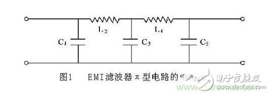
The low-frequency end portion is processed first, and the Chebyshev approximation is used for modeling. Chebyshev filter, also known as isosceles filter, exhibits equal fluctuation characteristics in the passband. The magnitude of the undulation marks the maximum deviation of attenuation from the ideal uniformity; the attenuation in the transition band has a ratio The Butterworth filter has a faster rate of growth; the attenuation within the stopband will show a monotonically increasing trend without considering the distribution parameters. According to the above technical requirements, it can be determined that the order of the Chebyshev filter is 5, and the connection mode of the components is divided into two types: T-type and π-type. The odd-numbered components of the T-type circuit are inductors, and the even-numbered components are capacitors. This requires a large number of inductors. In the actual fabrication of the filter, the size of the filter is mainly the size of the inductor. It is easy to use the T-type circuit. The filter is bulky and difficult to place, so most of the components are connected using a π-type circuit. The odd-numbered components of the π-type circuit are capacitors, and the even-numbered components are inductors. The circuit diagram is shown in Figure 1.
Due to the introduction of absorbing materials, the filter of the frequency band larger than 10 GHz can still guarantee the insertion loss of more than 100 dB, which overcomes the disadvantages of the traditional LC filter at the high frequency end due to the influence of the circuit distribution parameters, resulting in decreased or even completely failed filter performance.
1. introduction
In the past ten years, as the shielding room of the microwave experimental infrastructure, the frequency range of its application has been expanding, and the high frequency has been increased from 1 GHz to 18 GHz, even 40 GHz. It is expected that the future trend will increase to 60 GHz or even 100 GHz. In order to ensure the shielding effectiveness of the shielding room over the entire applicable frequency range, that is, the interference signal is not introduced or taken out of the shielding room due to the introduction of the power line or the signal line, which requires that the power supply filter and the signal filter of the shielding room are the same. The frequency range has the specified insertion loss.
The ultra-wideband electromagnetic interference EMI filter introduced in the paper is processed at the high end of the frequency by using the electrical loss or magnetic loss of the dielectric or magnetic medium to convert the high-frequency interference signal into heat, thereby achieving the filtering effect. The electromagnetic medium that we fill in the filter has a weak absorption effect on low-frequency electromagnetic waves and does not cause a large attenuation of the useful signal.
2. Design ideas for ultra-wideband EMI filters
The ultra-wideband EMI filter uses the LC reflection filter principle at the low end of the frequency and the absorption filter principle of the high performance absorbing material at the high end of the frequency. In the filter design process, the low-frequency end of the filter is first modeled according to the passband cutoff frequency, stopband insertion loss and rated current and leakage current provided by the demander, so that the required inductance and capacitance can be obtained. The number and the corresponding component values ​​are used to draw the corresponding circuit diagram. Since the EMI filter only needs to meet the required cutoff frequency and insertion loss, there is no special frequency response limitation. Therefore, the low frequency end modeling uses a Chebyshev filter response with simple circuit and few components, which can reduce the filter's Volume and weight.
The low-frequency end can only solve the frequency band below 100MHz. The frequency band above 100MHz may cause the performance of the LC filter circuit to drop or even completely fail due to the influence of the distributed inductance of the wires in the circuit and the distributed capacitance of the inductor coil. The high-frequency end processing method is to process a segment of the hollow coaxial line, and fill the inner and outer conductors of the coaxial line with a absorbing material with high magnetic loss and high electrical loss, and attenuate the high-frequency interference signal in the propagation path. A dielectric or magnetic medium filled between the inner and outer conductors of the coaxial line, such as ferrite, conductive carbon black, etc., is mostly a conductor, which may cause short-circuiting of the inner and outer conductors of the coaxial line, and an insulating layer between the inner and outer conductors is required for this purpose.
The low-frequency LC filter circuit has better insertion loss performance in the frequency band below 100MHz, but since the inductor coil and capacitor in the circuit are lumped parameter components, the distributed capacitance and capacitor in the inductor coil when the operating frequency is as high as 100MHz. The distributed inductance in the medium becomes a dominant parameter, which significantly degrades the insertion loss performance of such filters. At high frequencies, the coaxial line filled with the absorbing material has good insertion loss characteristics. If good EMI suppression is required from low frequency 10 kHz to microwave frequency 40 GHz, the two filters need to be connected in series, thus forming ultra-wideband EMI with low frequency reflection filtering and high frequency absorption filtering. Filter design ideas.
3. Application examples for ultra-wideband EMI filter design
Let us take the power filter as an example. Suppose the demand side has the following technical requirements: the passband cutoff frequency fp=1kHz, the stopband start frequency fs=10kHz, the passband attenuation is less than 3dB, the stopband attenuation is greater than 100dB, and the resistance is The band is extended to an upper frequency of 40 GHz.
The low-frequency end portion is processed first, and the Chebyshev approximation is used for modeling. Chebyshev filter, also known as isosceles filter, exhibits equal fluctuation characteristics in the passband. The magnitude of the undulation marks the maximum deviation of attenuation from the ideal uniformity; the attenuation in the transition band has a ratio The Butterworth filter has a faster rate of growth; the attenuation within the stopband will show a monotonically increasing trend without considering the distribution parameters. According to the above technical requirements, it can be determined that the order of the Chebyshev filter is 5, and the connection mode of the components is divided into two types: T-type and π-type. The odd-numbered components of the T-type circuit are inductors, and the even-numbered components are capacitors. This requires a large number of inductors. In the actual fabrication of the filter, the size of the filter is mainly the size of the inductor. It is easy to use the T-type circuit. The filter is bulky and difficult to place, so most of the components are connected using a π-type circuit. The odd-numbered components of the π-type circuit are capacitors, and the even-numbered components are inductors. The circuit diagram is shown in Figure 1.
Protection Relay,Protection Relay For Medium-Voltage Applications,Earth Leakage Relay,Smart Motor Protector
Jiangsu Acrel Electrical Manufacturing Co., LTD. , https://www.acrel-factory.com